Keep in mind, my speculations are based on my knowledge of how the Apple II works.
Which is, graphics wise, a total different beast than any other computer on this planet. It's basically analogue display digital encoded.
It's not NTSC. Czechoslovakia used SECAM at that time.
Which only affects colour, which in turn wasn't used at all, so it's all about a classic European 50 Hz B&W picture.
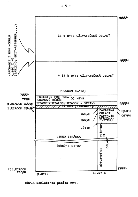
48 bytes equal 384 bits, but if each byte has 6 pixels, that could explain where the horizontal resolution of 288 pixels comes from, and neatly coincides with the 6-pixel wide stripes that share an attribute. Now, this is all speculation, so I'd appreciate if anyone can confirm this.
Exactly that way it is. Each byte holds six on/off pixels plus two used for attributes. In grayscale mode it did set the intensity for these 6 pixels.
memory is laid out 48 bytes to a scanline, and scanlines are 64 bytes apart,
That very much simplifies the design for the counters for a scan line length. All that's needed is a 6 bit counter, which is used generate the lower 6 bits of screen address, as long as its top bits are not 11. Feeding this counter with half the CPU clock (2,048 MHz) produced a line length of 64 µs, exactly (*1) what a line should be, while the output carrying part will be 48µs, so close and well within the allowed 52 µs (*2)
Similarly, the 256 lines are a way for needing only a single 8 bit line counter providing the address, and its carry as 'end of field' marker. An 8 bit line counter plus a 6 bit pixel (group) counter can now easily provide a 14 bit memory address. All what's needed to finalize is another counter (maybe even an analogue circuit) to define picture length.
so that there are 16 bytes' space available to the user, between those scanlines.
Yup, much like the screen holes on the Apple II. After all, video logic is here formed around the TV signal (just as in many machines). Just not as special as with the Apple.
So my question is how each byte is decoded. Those two left-over bits presumably encode an attribute of sorts, but that doesn't seem nearly enough to enable reasonable colour graphics.
Sure it does. It allows to either select two on/off attributes, or one with four values. On a colour output this can be used to give one colour to each switched on bit within that byte, and another to the next. Effectively giving 4 colours plus black on screen. So it's a bit like the restriction the Apple II got - just less weird.
Restricting colour to character positions has always been a common trick - just think C64 - here it's narrowed down to on colour selection per 6 horizontal pixel.
*1 - Well, it's a tiny bit less, but way within the tolerances defined.
*2 - Using the whole line width would have allowed 312 pixels to be shown, but now the 'comparator' would have been more complex than a simple 1/4 7400.

Pieštanský Mikropočítač Displejovýwhich translates tomicrocomputer with display from Pieštanybut everyone call itPomalý Malý Debilnýin translationSlow Small and Stupidmost likely due to fact you would need to remove and reinsert all the ICs every 3-6 months in order to keep it working ... but do not get me wrong it was fun playing with it ...