4

I have an archive of sample recordings with a sample playback program, the date and author in the BBC BASIC loader for the program is "(C) 1985 by DAVID J. HOSKINS"

There are are about 10 recordings, short clips including "James Whale All Hit Radio", Knight Rider TV series theme tune clip (file name NIRIDER), Vincent Price Laughing [off Michael Jackson's Thriller song, at end] (file name: VPLAUGH)

The 6502 machine code is as follows for the audio playback, as a hex dump:

           00 01 02 03 04 05 06 07 08 09 0A 0B 0C 0D 0E 0F

00000000   78 A9 C1 20 67 09 A9 00 20 67 09 A9 81 20 67 09  x©Á g.©. g.© g.
00000010   A9 00 20 67 09 A9 A1 20 67 09 A9 00 20 67 09 A9  ©. g.©¡ g.©. g.©
00000020   00 85 70 A9 22 85 71 A0 00 B1 70 48 29 0F 20 51  .…p©"…q .±pH). Q
00000030   09 A6 72 CA D0 FD 68 4A 4A 4A 4A 20 51 09 A6 72  .¦rÊÐýhJJJJ Q.¦r
00000040   CA D0 FD E6 70 D0 02 E6 71 A5 71 C9 7B D0 D8 58  ÊÐýæpÐ.æq¥qÉ{ÐØX
00000050   60 49 0F 48 09 D0 20 67 09 68 48 09 90 20 67 09  `I.H.Ð g.hH. g.
00000060   68 09 B0 20 67 09 60 A2 FF 8E 43 FE 8D 4F FE E8  h.° g.`¢.ŽCþOþè
00000070   8E 40 FE EA EA EA EA A2 08 8E 40 FE 60 00        Ž@þêêêê¢.Ž@þ`.

Which disassembles to:

                  * = 0000

0000   78         SEI
0001   A9 C1      LDA #$C1
0003   20 67 09   JSR $0967
0006   A9 00      LDA #$00
0008   20 67 09   JSR $0967
000B   A9 81      LDA #$81
000D   20 67 09   JSR $0967
0010   A9 00      LDA #$00
0012   20 67 09   JSR $0967
0015   A9 A1      LDA #$A1
0017   20 67 09   JSR $0967
001A   A9 00      LDA #$00
001C   20 67 09   JSR $0967
001F   A9 00      LDA #$00
0021   85 70      STA $70
0023   A9 22      LDA #$22
0025   85 71      STA $71
0027   A0 00      LDY #$00
0029   B1 70      LDA ($70),Y
002B   48         PHA
002C   29 0F      AND #$0F
002E   20 51 09   JSR $0951
0031   A6 72      LDX $72
0033   CA         DEX
0034   D0 FD      BNE $0033
0036   68         PLA
0037   4A         LSR A
0038   4A         LSR A
0039   4A         LSR A
003A   4A         LSR A
003B   20 51 09   JSR $0951
003E   A6 72      LDX $72
0040   CA         DEX
0041   D0 FD      BNE $0040
0043   E6 70      INC $70
0045   D0 02      BNE $0049
0047   E6 71      INC $71
0049   A5 71      LDA $71
004B   C9 7B      CMP #$7B
004D   D0 D8      BNE $0027
004F   58         CLI
0050   60         RTS
0051   49 0F      EOR #$0F
0053   48         PHA
0054   09 D0      ORA #$D0
0056   20 67 09   JSR $0967
0059   68         PLA
005A   48         PHA
005B   09 90      ORA #$90
005D   20 67 09   JSR $0967
0060   68         PLA
0061   09 B0      ORA #$B0
0063   20 67 09   JSR $0967
0066   60         RTS
0067   A2 FF      LDX #$FF
0069   8E 43 FE   STX $FE43
006C   8D 4F FE   STA $FE4F
006F   E8         INX
0070   8E 40 FE   STX $FE40
0073   EA         NOP
0074   EA         NOP
0075   EA         NOP
0076   EA         NOP
0077   A2 08      LDX #$08
0079   8E 40 FE   STX $FE40
007C   60         RTS
007D   00         BRK
007E              .END

It takes a few parameters from the calling BBC Basic program, one of which is playback speed. At the time, I did disassemble this successfully and incorporate this assembly into my own Utility-ROM as a *PLAY command for BBC Master, a la "C64's Simon's Basic" to provide extra utilities via easy to use star commands. It was my GCSE Computer Studies project in 1989, called "System PLUS". I don't have the same tools easily to hand but I might be able to re-run the disassembly under emulator for BBC micro and update the answer.

What bit depth might the samples have? I read that with the AY-8912 sound chip, that there was a esotetric technique / trial and error to work out a bit depth of 5 bits. I will try to find the name of the technique.

Were each sample linear or logarithmic?

What was the sample rate of the playback?

Curiously, documentation for a Speech Synthesizer for the BBC suggested 8 bits logarithmic was possible, cited here: https://retrocomputing.stackexchange.com/a/17206/8111
3
  • " I read that with the AY-8912 sound chip," - which BBC Micro had an AY-8912? Commented Apr 3, 2021 at 19:42
  • I think Exile BBC Game used audio samples for some sounds, using a similar or same playback technique. Commented Apr 3, 2021 at 21:44
  • A disc with (some of) these samples can be found at 8bs.com/pool/bbc/bbc22.zip . Though the filenames and BASIC loaders have been modified over the years, the player is identical (as presumably is the sample data, although oddly some files are 512 bytes bigger than others).
    – hexwab
    Commented Apr 9, 2021 at 22:11

4 Answers 4

6

Here's how the specific routine you posted works. It appears to be using the "4-bit linear" method mentioned on this page. The resulting samples are not truly linear, but it's easy to understand and implement, and good enough for game SFX or speech.

We'll analyse this in bottom-up order, starting with the last routine, which simply takes a command in the accumulator and sends it to the sound chip, which in the BBC Micro is attached to the "slow bus" on the System VIA. Other devices on the "slow bus" are the Speech chip (if fitted, but it rarely was) and the keyboard.

$0967:
   LDX #$FF
   STX $FE43  ; System VIA Port A, all bits output direction
   STA $FE4F  ; System VIA Port A, place accumulator on wires, no handshake
   INX
   STX $FE40  ; System VIA Port B, assert sound chip write strobe
   NOP : NOP : NOP : NOP  ; sound chip is really slow
   LDX #8
   STX $FE40  ; System VIA Port B, negate sound chip write strobe
   RTS

The above routine is called extensively by the rest of the playback code. The general pattern is "load some value into A, then JSR $0967". I'll abbreviate that to "send command whatever's in A to the sound chip".

The immediately preceding routine takes a single 4-bit sample and sets the volume of all three tone channels to it:

$0951:
   EOR #$0F    ; SN76489 takes a negative volume level
   PHA
   ORA #$D0    ; command: set volume of Channel 2
   JSR $0967
   PLA
   PHA
   ORA #$90    ; command: set volume of Channel 0
   JSR $0967
   PLA
   ORA #$B0    ; command: set volume of Channel 1
   JSR $0967
   RTS

Obviously it would be entirely feasible to have one channel playing samples while the two others (and the noise channel) were doing their normal job, and that would make the above routine far shorter. That sort of technique is used extensively in the demoscene these days.

Most of the rest of the code is just extracting two 4-bit samples from each byte, then sending them to the sound chip as above, with a delay routine for timing. That loop begins at $0927.

$0927:
   LDY #0
   LDA ($70),Y  ; fetch byte from sample array
   PHA
   AND #$0F     ; extract low nybble
   JSR $0951    ; send sample to sound chip
   LDX $72      ; load delay value
:  DEX
   BNE :-       ; delay loop
   PLA
   LSR A        ; extract high nybble
   LSR A
   LSR A
   LSR A
   JSR $0951    ; send sample to sound chip
   LDX $72      ; load delay value
:  DEX
   BNE :-       ; delay loop
   INC $70      ; advance pointer to next sample byte
   BNE :+
   INC $71
:  LDA $71      ; check for end of sample array
   CMP #$7B
   BNE $0927
   CLI          ; at end, re-enable interrupts and return
   RTS

The delay value pre-loaded into $72 would determine how many samples per second, and thus how long the sample was, given that there's a fixed number of samples. The minimum delay (1) would correspond to about 10kHz, giving a sample length of about 4.5 seconds. The maximum delay (0, meaning 256 loops at 5 cycles each) would give only about 1.35kHz, which is not enough for even telephone-quality speech.

Prior to the main loop, there is an initialisation routine. Most of this is concerned with setting all three tone channels to a divisor of 1, which on most SN76489 variants produces a high DC output instead of a square wave; this can then be modulated by the volume register.

$0900:
   SEI   ; disable interrupts, avoiding interference from keyboard
         ; scanning which would change the System VIA configuration,
         ; and from BBC Micro's built-in sound routines
   LDA #$C1 : JSR $0967  ; command: low nybble of Channel 2 tone divisor to 1
   LDA #$00 : JSR $0967  ; command: high byte of tone divisor to 0
   LDA #$81 : JSR $0967  ; command: low nybble of Channel 0 tone divisor to 1
   LDA #$00 : JSR $0967  ; command: high byte of tone divisor to 0
   LDA #$A1 : JSR $0967  ; command: low nybble of Channel 1 tone divisor to 1
   LDA #$00 : JSR $0967  ; command: high byte of tone divisor to 0
   LDA #0
   STA $70  ; low byte of sample array start address
   LDA #$22
   STA $71  ; high byte of sample array start address

This falls through straight into the main loop.

The sample array extends from $2200 to $7AFF inclusive, a total of 22784 bytes or 45568 samples. Since MODE 7 display memory starts at $7C00, the small amount of unused memory after the array was probably reserved for the variables of a small BASIC program. I assume this was used to assemble the above routine, load the samples from disk, preset $72, and present a simple UI to the user.

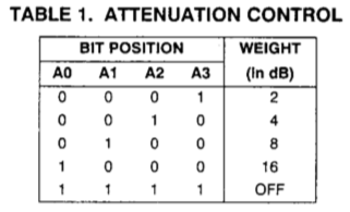
According to the datasheet, the volume control (actually an "attenuator" which is why it seems negated) produces a logarithmic result, as the weights of each bit in the volume register are defined in terms of a decibel attenuation:

volume register

This could be accounted for by pre-processing the audio before packing it into nybbles and bytes. I assume this demo didn't do that, however; it's not very tightly coded.

3
  • +1 and accepted answer for the detailed analysis, reverse engineering and research. One question: "Obviously it would be entirely feasible to have one channel playing samples while the two others (and the noise channel) were doing their normal job, and that would make the above routine far shorter. That sort of technique is used extensively in the demoscene these days." - why did the code use all three channels instead of your suggestion that 1 could be used? Could using all 3 provide better playback quality? Commented Apr 5, 2021 at 14:25
  • 1
    @therobyouknow I assume they just wanted it as loud as possible, since the BBC Micro's built-in speaker isn't very big or powerful. Since they weren't using the other channels for music, all of them were available for power.
    – Chromatix
    Commented Apr 5, 2021 at 16:11
  • +1 thank you @Chromatix - yes, ah, I can imagine that sampled playback would be a bit quieter than the bold square wave tones so I see what you mean! Commented Apr 6, 2021 at 9:09
5

The BBC Micro uses an SN76489, which provides three tone channels each with sixteen volume levels. For speech playback the standard approach is to set the channels in use to a very high frequency and then modulate the volume.

For each channel the volumes are a logarithmic scale, where each step is approximately 10^-0.1 as loud as the previous, i.e. around 79%.

You can of course change only one volume at a time; if you want to use multiple channels to increase resolution then you can go the native route of just hoping the user won’t be too strongly bothered by the unclean transitions between sample levels, or you can use the Viterbi algorithm to transition only one channel at a time while minimising error from the original — think of the single-channel steps as the hidden states and the desired output levels as the observed states.

So it is reasonably valid, though not quite exact, to look at summing the three channels to induce a single output.

Running the numbers, I get 1114 total potential volume levels, but they’re nothing like linearly spaced; if I force them onto a 8-bit integer scale I get only 180 different values.

So I’m going to say that with modern preprocessing you can get something only a little worse than 8-bit linear output.

As to a sampling rate, I’m willing to take the linked Speech article at its word and assume that 10,000 single-channel transitions per second is accurate; for most audio that won’t sound too much worse than 10kHz though, again, you should be thinking of output that is getting 10,000 opportunities per second to reduce its divergence from the true original rather than necessarily 10,000 completely independent samples.

On a BBC, unless you’ve gone off piste with custom hardware, you’re going to run up against storage limitations a long time before anything else becomes troublesome, I think, unless you like being able to play only a second or two of audio at a time.

1
  • +1 upvote thank you Tommy - good detail in the answer. Some more info, from my memory, regarding the mentioned recordings: the Vincent Price laugh recording lasts 3-5 seconds, similar time for the Knight Rider theme clip (it's the voice over bit). Quality in relative terms was impressive for back then - mid 80s on an 8 bit machine - recognisable audio. In absolute terms it's probably worse than conventional POTS telephone call quality, with the "crunchyness" audible artifact of low bit depth. Commented Apr 3, 2021 at 21:43
2

Here is an example of what the modern preprocessing Tommy is alluding to actually sounds like: er1.ssd er2.ssd er3.ssd.

This is encoded using pcmenc, storing 4-bit volumes for each of the three tone channels in turn, evenly spaced at 35294Hz, so this is 12-bit sampling at 11.7kHz or 4-bit sampling at 35.3kHz depending on how you want to look at it. At an effective data rate of ~17K/sec, 92K of sample data gets you just over five seconds of audio (yes this is BBC Master only). I imagine this could usefully be compressed but right now I got nuthin'.

The tone channels are set to the highest possible frequency of 125kHz so that their volume prior to attenuation is effectively constant after subsequent lowpassing (albeit at only half the maximum volume; this is another reason you really want to use all the channels). This is not quite the same as saying that writing a period of 1 produces constant DC output (and while we're on the topic, writing a period of zero wraps around to 1024, a common source of emulator bugs).

Here's the source for the player but there's very little to it: set all the tone channels to maximum frequency, set up a free-running timer, busy-wait until it goes off, dump a byte out to the sound chip, increment your pointer and repeat until you run out of data.

The only real differences between this and David Hoskins' code are the use of a timer rather than cycle counting[1], and storing separate volumes per channel rather than repeating the same data across all three of them.

A couple of things that make this kind of routine extra-annoying on the Beeb are that the SN76489 latches data on the falling edge of ~WE, so you can't just hold ~WE low but have to manually lower and raise it for every byte you send, and the READY pin is not hooked up to anything so you can't measure how long your particular sound chip actually takes to latch but have to be pessimistic (datasheet suggests 32 cycles or 8µs at 4MHz).

Let's not forget that the slow data bus is also used by other devices. While you can simply set DDRA every time in your "write byte to sound chip" function, as both David Hoskins' code and the similar routine in the OS ($EB21 in OS 1.20) do, this is inefficient if you're in a tight loop with interrupts off. It's also worth trying to perform whatever computation you can in the 8µs=16 CPU cycles you have to hold ~WE low, not forgetting that 8µs is just a minimum and the precise timing is unimportant (non-sample player example).

The use of a timer suggests an interrupt-based routine rather than busy-waiting but because the latency between an interrupt firing and actually getting control via IRQ1V is around 30 cycles again this is annoyingly hard on the Beeb.

But not quite impossible. (source)

Running the included benchmark program shows that it uses about 50% CPU time, and that is only possible because this particular sample, being heavily filtered, has gaps where we don't have to play (or store) anything and can thus return control to the OS briefly.

Sadly this did not make it into BEEB-NICCC.


[1] Except that it turns out that 35kHz is high enough for a timer to be ineffective so I ended up counting cycles anyway. But you can still change the timer value at ?&E1C and eventually you can make it slow enough to make a difference.

0
0

The volume/attenuation don't seen to be quite logarithmic, but that may be due to using multiple waves at the same frequency being synchronised for double volume or cancelled to 0. It may be better to use frequencies 1, 2 and 4 to get a more consistent output.

I have used the noise channel in my sample playback, although it didn't improve the quality, it does extend the possible output values.

I don't believe that the data is latched as described as writing different values without latching does change the output, but is not reliable, so the method described is still best. To this end, you can write upto but not including every 16us but you can still run code while waiting.

The frequency 0 for DC comes from the SEGA Master System where 0 does just enable the channel and make sample playback much louder. There is an excellent description of the chip and its varieties here https://www.smspower.org/Development/SN76489

For emulating earlier arcade games, the simplicity of the game can mean that sample playback is a good option for mimicking the analogue circuitry used in them. My version of Space Invaders with samples shots and alien explosions is in this post https://stardot.org.uk/forums/viewtopic.php?p=328825#p328825

You must log in to answer this question.

Not the answer you're looking for? Browse other questions tagged .