30

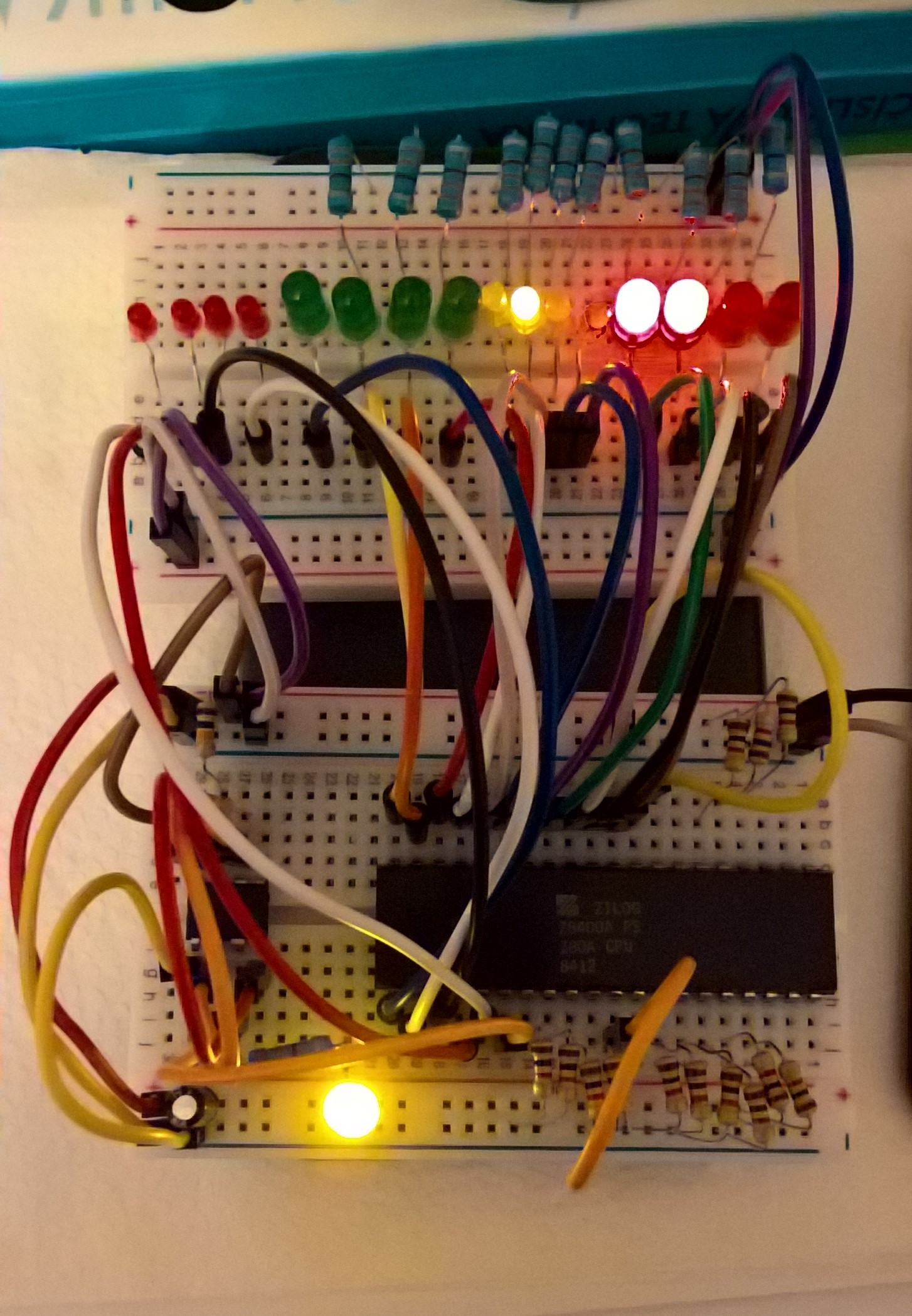
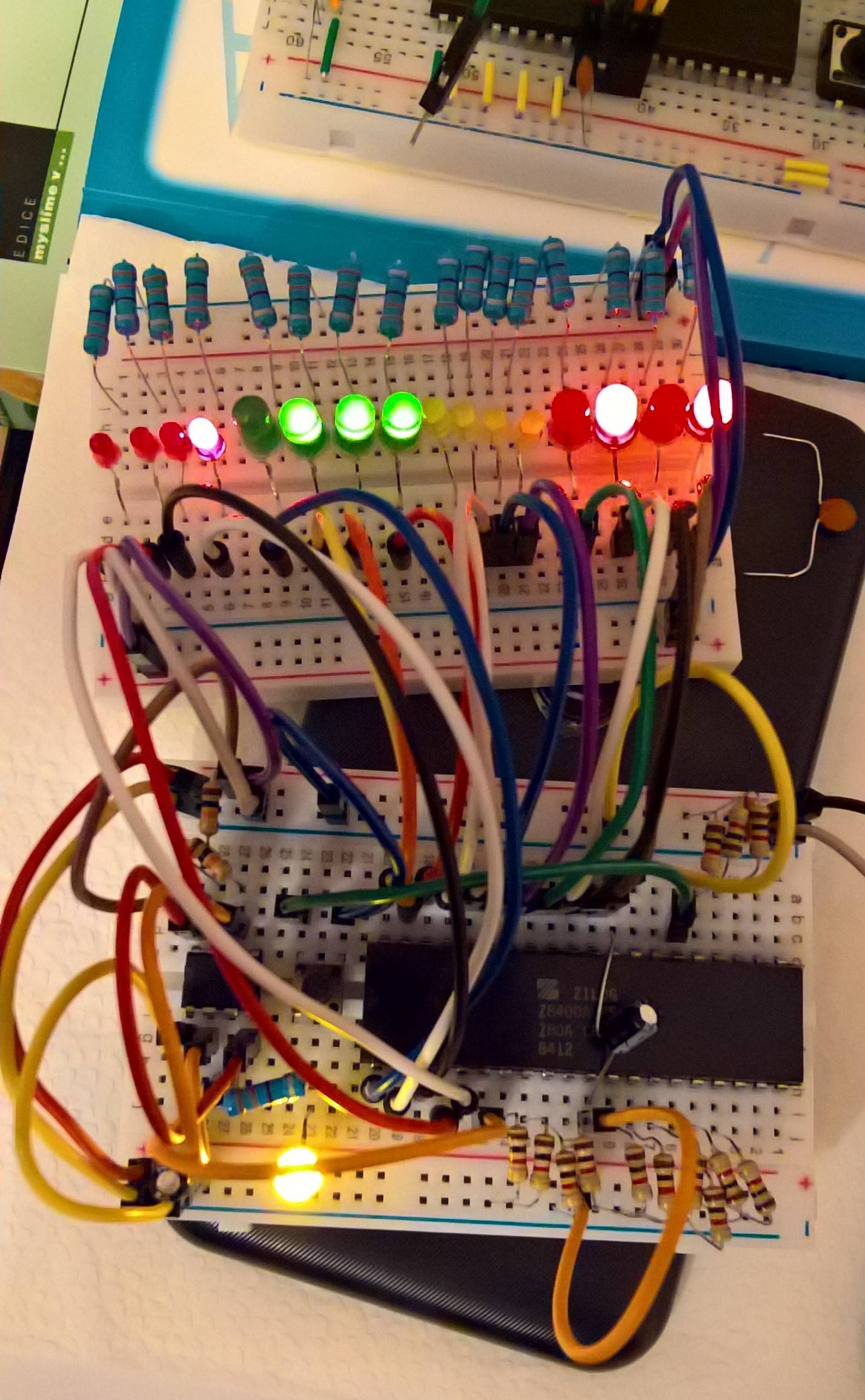
A few days ago, I got Z80A CPU from eBay. So I tried to run it with classic 555 timer as a clock signal generator. I connected the 8-bit data bus of the CPU to the ground to "simulate ROM" (00 for NOP). I wired up all missing inputs: WAIT pin 24, pin 16, 17, 25, 26 to the 5V. And all address bus pins to LEDs to see the NOP, how it behaves. Normally it should count up to 2^16 without any problems, but it randomly freezes somewhere. I also tested my 2nd Zilog Z80C version with the same circuit and it works just fine.

What could cause the freezing of the CPU? Is the CPU defective?

Zilog Z80A on breadboard

Edit (solution): The problem was solved with blocking capacitor between + and - on breadboard (row 2), decoupling capacitor between +5V and GND on the Z80 and with the reset button. Thank you for all the answers.

Solution

4
  • 9
    The fact your second test worked fine seems like a hint. Did you ever retest the first Z80, to eliminate maybe something spurious that caused it to fail?
    – Brian H
    Commented Feb 3, 2020 at 18:16
  • 8
    1. I do not see any blocking capacitor near CPU power supply pin 2. is your CPU clock inside specs range (some technologies do not work on too low frequency) ? 3. Breading board is not very reliable with higher frequencies ...
    – Spektre
    Commented Feb 3, 2020 at 18:28
  • 6
    My suspicion: Insufficient decoupling, too many leds being switched at once, brownout, THUNK! Commented Feb 4, 2020 at 14:05
  • 2
    What the lowest possible number for the count? If it's 0, note that a 16-bit counter cannot reach 65 536 (2^16) - there aren't enough bits to hold that number.
    – user6030
    Commented Feb 4, 2020 at 22:25

2 Answers 2

56

There are many issues here.

  1. As it is already said in comments, decoupling capacitor is a must!

  2. 555 (non-CMOS) timer output is very much like the output of TTL ICs, however Z80 requires a firm logic one. When feeding Z80 clock pin from a TTL output, you should use pullup resistor of 200..500 Ohm.

  3. NMOS Z80 uses dynamic logic, that means it has some minimal clocking frequency, and it won't work at all if your clock is much less than datasheet's minimal frequency (or a datasheet's maximal clock period).

  4. You should also initialize Z80 with the /RESET signal lasting several clocks before ever hoping to get anything sane from the CPU.

The easiest way to get Z80 working in your configuration is to swap it to CMOS version, which is fully static (i.e., it has no limit to how slow the clock might be). Additional attention must be paid to get clock levels right (swap TTL 555 to CMOS one like TS555 or add a pullup resistor) and decoupling capacitors to both 555 and Z80. Finally, add a reset button and keep it pressed for several clocks in the beginning.

2
  • 11
    What a fine analysis from the meagre information given +2
    – Raffzahn
    Commented Feb 3, 2020 at 20:26
  • Good answer, it is important to note that while the Z80 is fully static it is very susceptible to noise (hence the need for the decoupling cap). Rather un-intuitively, the slower the clock the more susceptible it becomes to noise. Showed up for me when building a single-step/slow clock circuit.
    – Tim Ring
    Commented Mar 18, 2020 at 16:08
14

I'd just like to expand on a couple of points in lvd's excellent answer.

Reset Circuit

You might get by with just using a jumper wire to short the reset pin to ground for a brief moment after you've powered up the CPU. It's worked for me, but if you're having problems it's best to build a proper reset circuit.

Many CPUs have a minimum length for the reset pulse. If your reset switch isn't debounced, it might generate a perfectly fine result pulse but then bounce on release, leaving you with a too-short pulse (and possibly a confused CPU) after that.

A 555, of which you clearly already have at least one, works well to generate a pulse of a specific length; just wire it up as a one-shot. Gates with Schmitt-trigger inputs, such as a 74LS14, are also great for generating pulses and debouncing switches, and you can use an spares as regular gates (for address decoding or whatever) as well.

Some examples of the above circuits, and a good introduction to reset circuits, are given in the Reset Circuits section of Wilson Mines Co. 6502 Primer. I strongly encourage you to read through the relevant pages in that primer as you build sections of a computer, such as the clock, reset circuits, address decoding, etc. etc. It will give you a general understanding of the problems and solutions in each area and also give a lot of specific advice on how to avoid pitfalls.

Decoupling Capacitor

Regarding the decoupling capacitor, 0.1 μF is a typical value; just drop one lead of the cap into the the breadboard column for the Vcc pin and the other into the breadboard column for the ground pin of that chip. (This goes right over the top of the chip for the Z80.) If the two pins are too far apart, and you don't want to take the time to extend the cap with a wire, even just using an adjacent ground rail will still help enormously.

You should do this for all your chips, not just the CPU.

If you have an oscilloscope, run your system with a 1 MHz clock and, with and without the decoupling capacitor, have a look at the waveforms of your clock input and an output such as A0. Freqently you will get a pretty dramatic demonstration of what a decoupling capacitor does for you.
5
  • 2
    usual power on reset circuit is just a simple RC filter ... for example for /RESET cap ~10uF is grounded (-pin) and pulled up (+pin) by ~12K to Vcc (+5V) and the common connection between R and C is connected also to /RESET pin. No need for timing IC ... On power on the cap is empty so its start charging so the /RESET is LOW until the voltage on cap reaches TTL barrier voltage ... You can also add a micro-switch parallel to capacitor (optionally with few ohms R to limit current). The RC values create the timing constant I used just some safe values that work across many CPU/MCUs
    – Spektre
    Commented Feb 4, 2020 at 8:19
  • 4
    Then you need at least a diode that won't allow /RESET pin to overvoltage when powering off. If your device has some type of flash storage, it might be damaged during power-off, since such circuit does only power-on, and not a brown-out reset.
    – lvd
    Commented Feb 4, 2020 at 10:52
  • 2
    @Spektre (Just so he gets a notification about lvd's response.)
    – cjs
    Commented Feb 4, 2020 at 14:58
  • @CurtJ.Sampson yep I got it ... :) and I also know the diode protection , but had never a problem without it as digital input gates are usually at risc just from over voltage and reverse polarity. The current reversal is more of a problem in analog ICs and linear voltage regulators ...
    – Spektre
    Commented Feb 5, 2020 at 9:29
  • I would recommend a bulk decoupling capacitor as well, particularly in a lash-up like this. 10 uF to 47 uF across the 5 V supply on the breadboard itself should be plenty.
    – TonyM
    Commented Feb 5, 2020 at 22:58

You must log in to answer this question.

Not the answer you're looking for? Browse other questions tagged .