11

With modern IDE controllers it is simple to find the correct way to plug a cable:

cable port

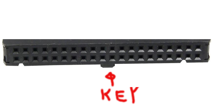
The cable must be inserted with the sticking-out key part up (to match the notch in the plastic cover)

Now look on this old controller:

old controller

Where to put the key part? Up or down?

For people who don't know the key (like me before I read the comments to question), I put image with the key (please don't laugh at the quality)

the key

1
  • 8
    This question makes me feel old. In the 90s, when we assembled a PC, one of the first things learned was "there's always some kind of marker for pin 1 on cable and socket and those have to line up ... and if there isn't, you're f****". I guess this got so ingrained that I didn't anticipate someone asking that question. :) (Also, one correction: "male" generally refers to the connector having pins, "female" for having holes. I also think we need different terms for that; this genital reference feels off-putting nowadays.)
    – orithena
    Commented Feb 2, 2023 at 16:59

3 Answers 3

31

This answer is also generic to other applications using this sort of connector (confusing known as IDC- insulation displacement connector), which may have just about any number of pins, not just the 40 for IDE.

On the photo (2nd photo) of the controller, you can see (at right) pins numbering for 39 and 40. This means that pin 1 is at left. Note that any IDC connector will have a pin 1.

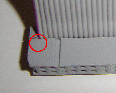
The connector in the third photo will also have a small arrow pointing to pin 1. It's not visible in the photo, but you can see it in one of the photos (Pin_1_idc.png) in the page linked above.

photo showing arrow from https://en.wikipedia.org/wiki/Insulation-displacement_connector

Thus, all you need to do is align the pin 1 marking on the connector to the pin 1 marking on the controller.

4
  • 23
    Also the edge of the ribbon at the pin 1 end is often marked with a contrasting color. Most often red, as shown in your picture, but sometimes a dark blue or black stripe. I've also seen dark cables where the stripe is light.
    – Sotto Voce
    Commented Feb 2, 2023 at 0:04
  • Why do you say the IDC name is confusing?
    – Hearth
    Commented Feb 5, 2023 at 2:07
  • @SottoVoce Exactly. I always understood "pin 1 = different color on the cable" and the only other thing was to figure out which pin was pin 1 on the connector. And if it wasn't labeled on or next to the connector, it would normally be (as in this example) on the left end relative to the printed label. Commented Feb 5, 2023 at 2:36
  • @Hearth just to point out that it's different to the similarly named IDE, the point being that having knowledge of IDC cables will help in the specific case of IDE.
    – user85471
    Commented Feb 5, 2023 at 21:03
10

In this case the pin numbers are marked, which makes it straightforward like user85471's answer shows. But if that is not the case, you can use a multimeter or a continuity tester.

This method will work for most cables that have multiple ground pins.

  1. Locate the pinout for the connector. For example from wikipedia.
  2. Find two pins that are both connected to ground. For example 2 and 40 are easy to locate because they are at the corners opposite the tab.
  3. Measure continuity between those pins in both possible orientations. If you get continuity only in one orientation, you know that is the correct one.
  4. Sometimes unrelated IO pins can show continuity in the opposite orientation, in that case retry with different set of ground pins.

For two layer PCBs, you don't necessarily need to even measure - it is directly visible what pins are connected to a ground plane.

1
  • 5
    A better test would be to, rather than testing between pins, locate a ground on the board (or a different connector) and test to that.
    – jaskij
    Commented Feb 2, 2023 at 16:07
9

Generically, when designing a PCB it is common practice for through-hole connector footprints to have round pads, except for pin 1 which is square. This can often be seen on the reverse side of the PCB - if one of the pads is square and the rest are round, it's likely that square pad is pin 1.

Since you know pin 1, you can line it up with the arrow on the connector and stripe on the cable, as described in another answer.

You must log in to answer this question.

Not the answer you're looking for? Browse other questions tagged .