My first answer attempts to answer all the OP's questions without going too deep into the hardware details. Since posting that answer, I have had the pleasure of corresponding for several days with Bil Herd, the lead designer of the C128 project. In addition to what I have learned from him, I have done some additional research on my own.
This answer focuses on the hardware complexities which limited CP/M's effectiveness on the C128. It won't shy away from displaying system diagrams, timing diagrams, and etc. If you don't care about this level of detail, cool, and you have been warned. 🤖
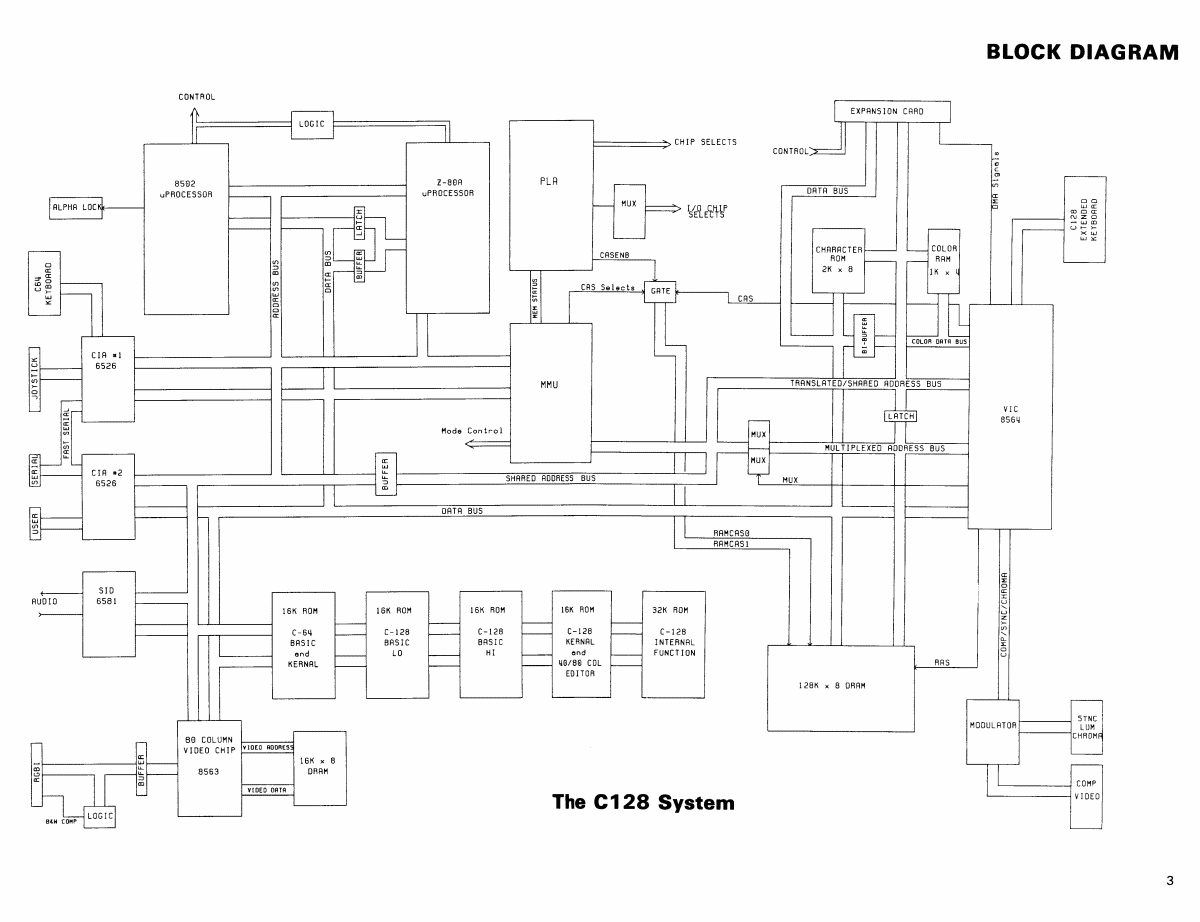
Here is the System Diagram, taken from page 3 of the C128 Service Manual (C128SM - click to expand):
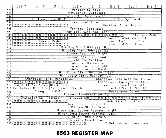
 Remember the big deal I made of the 80-column 8563 Video Display Controller in my first answer? That's the tiny bit in the lower left corner. It is almost completely isolated from the rest of the machine, except for the address and data buses. That is why communication with the 80-column video RAM takes place via two registers of the 8563. The 8563 has 37 registers total, allowing control of number of characters per line, number of lines, cursor position, video synch, etc.
You might be thinking, "There is a lot going on in that diagram." Yes. The C128 is essentially 4 computers in one box:
- a C64 with almost total compatibility, with the 8502 (upgraded 6502) running at 1 MHz and driving the 40-column VIC display
- a low-res C128 driving the 40-column display and running the 8502 at 1 MHz
- a high-res C128 driving the 80-column display and running the 8502 at 2 MHz
- a Z80A computer for running the CP/M operating system. It runs at 4 MHz, "half the time".
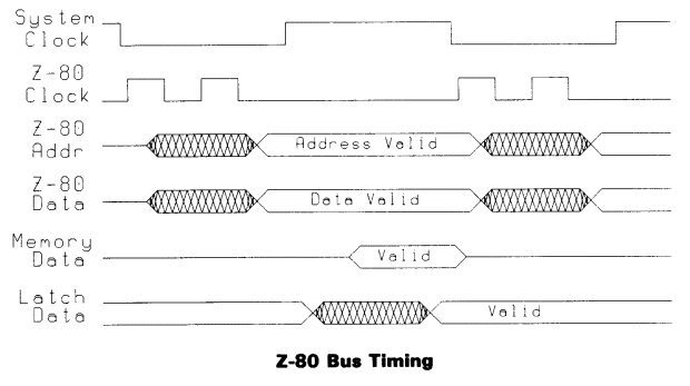
"Huh?" A diagram is in order, from page 8 of the C128SM:

"Okay, I sort of get it. The Z80 clock is only running half the time. I see it, but that does not explain why?." The system clock is a 1 MHz clock provided by the VIC chip. In modes #1 and #2 it lets the 8502 run half the time, and allows itself half the time to update 40 column video RAM, move sprites, etc. One nice thing about 6502-family chips is that turning over half their time to something else costs them nothing, so they share with other stuff on the bus easily. In mode #3 it runs at 2 MHz and drives the 8502 at 2 MHz. Since the 40-column display is not active, the VIC need not worry about sprites and ignores the 40-column video RAM. Note, though, that this 2 MHz mode would not help the Z80A; at best it would simply force that chip into a semi-even 2 MHz mode.
Here is the kicker, why the VIC must keep running even when 40-column video is not active (from pg.33 of same manual):
The VIC chip contains a register which allows the C128 system to operate at 2 MHz instead of the standard 1 MHz of the C64. This operating speed, however, disallows the use of the VIC chip as a display processor. This bit is bit zero in register 48, and setting this bit enables 2 MHz mode. During 2 MHz operation, the VIC is disabled as a video processor. The µProcessor spends the cycle full time on the bus, while VIC is responsible only for dynamic RAM refresh and DMA arbitration. Clearing this bit will bring back 1 MHz operation and allow the use of the VIC as a video display chip. During refresh and I/O access, the system clock is forced to 1 MHz regardless of the setting of this bit.
(emphasis mine)
Rephrasing, if the VIC were completely shut off, the system's RAM would not be refreshed, and memory data would degrade. Also the VIC is forced to 1 MHz mode during refresh and I/O. Thus it makes no sense to use the 2 MHz VIC mode with CP/M because nothing is gained in the first place, and it would keep having to switch back to 1 MHz anyway. (The 8563 refreshes its 80-column memory asynchronously with everything else.)
There is even another reason for keeping the VIC alive during CP/M. Look again at the C128 System Diagram, focusing on the upper right corner. See the little box labeled C128 Extended Keyboard? What is that about?

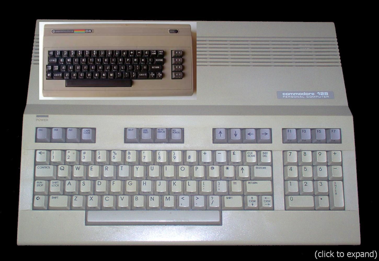
Imagine using a business application with just the C64 keys. To get the rest, the VIC needs to be active. Well, "the rest" except the CAPS LOCK at the top of the keyboard. It operates as a simple switch, separate from the 2-dimensional keyboard matrix, and its value is fed directly to the 8502 CPU. That means the Z80A cannot read that one key directly. However, since normal CP/M I/O is indirect and utilizes the 8502 and its BIOS, that key value is available. Only a pure Z80A routine lacks access. However, such a routine would be affected by the value of the separate SHFT LOCK key.
The Display Bottleneck
Writing a character string to the 80-column screen from CP/M involves multiple layers of code:
- application layer - executes a printf() or other function to display a string
- BDOS layer - device-independent I/O handling for CP/M. BDOS can handle a full string, but must call steps 3-8 character by character.
- BIOS layer - sets up "memory mailboxes" so 8502 CPU can know what to do
- Z80A turns over control to 8502
- 8502 obtains command from mailbox and readies itself to make BIOS85 call
- 80-column screen-write call executes.
- 8502 returns control to Z80A
- BIOS returns to BDOS
- BDOS sends next character to step 3 or returns to application code
(Note that a native 8502 application would avoid most of these steps.)
Lets look at the heart of step #6 as an 8502 disassembly, beginning at location 0181F (not the actual BIOS85 code, just an example of what it needs to do).
0181F  A2 1F     LDX #$lF  ; 8563 R/W data register number
01821  8E 00 D6  STX $D600 ; location of 8563 command register
01824  2C 00 D6  BIT $D600 ; check high bit of command register value
01827  10 FB     BPL $1824 ; loop until clear
01829  8D 01 D6  STA $D601 ; (8563 data register) write character to screen
0182C  60        RTS       ; return
All 80-column screen communication occurs through the two 8563 registers, mapped to memory locations $D600 and $D601. Figure 10-2 illustrates this, from page 295 of the C128 Programmer's Reference Guide.
 $D600 tells which of the thirty-seven 8563 registers you wish to read or write, and $D601 is the location to read or write the data. Since the 8563 is often occupied with its own memory and driving the 80-column screen, it can take time to handle the $D601 value. That's why you must always check the $D600 STATUS bit before reading from or writing to $D601. One useful feature of writing to register 31 (data register) is that the screen location auto-increments after the write. You need not manually increment it.
Don't assume the 8563 has a poor design. Normal (non-CP/M) 80-column C128 programs run with no noticeable delay in screen writes. The CP/M bottleneck is not the chip itself; it is the many layers of code through which screen writes must undergo.
It is one busy chip; everything else in this answer relates to its digital functionality. Don't forget that it drives the video as well, converting bytes in memory to a 4-channel per pixel video signal (RGBI). Most of what it is doing is invisible to the 8502/Z80A side of the board. If set to its normal 80x25 screen, that is driving:
- 80*9 pixels per scan line
- 25*9 scan lines (each 8x8 character can be embedded in a larger frame)
- 60 screen refreshes per second
- = 720 * 225 * 60 = 9.72 million pixels per second
Time is also allocated for horizontal and vertical synchronizations. Modify the synch values, and it can generate screens of more than 88 characters by 30 lines. Turn on interlace, and you can even double the number of scan lines. That's the output end.
From video RAM it must read the 80 character codes per line, read the associated byte of attributes for each character (color bits for (red, green, blue, intensity), as well as modifier bits for (alternate character set, reverse, underline, blink)). Finally it has to read the character definition RAM so that it knows what each character looks like. The 8563 character RAM is loaded during system boot-up, and both of its 256-element sets of 8x8 characters can be redefined by application programs. Internally I'm sure that some of the data is buffered within the 8563 (such as the current and maybe next character lines of data), but I don't know. The point is, no matter what's going on with the I/O ports at $D600 and $D601, the 8563 is extremely busy doing its job of displaying the screen. One more thing – because neither C128 BASIC 7 nor CP/M support it, few people realize the 8563 can also operate in a 2-color bit-mapped mode.
... not a poor design at all. I'll end with showing the 8563 register map to give you an idea of all the things this chip is handling. This is from page 37 of the C128SM.


