8

Pax Electronica Japan XT Pax Electronica Japan XT Cassette Port Pax Electronica Japan XT Cassette Circuit

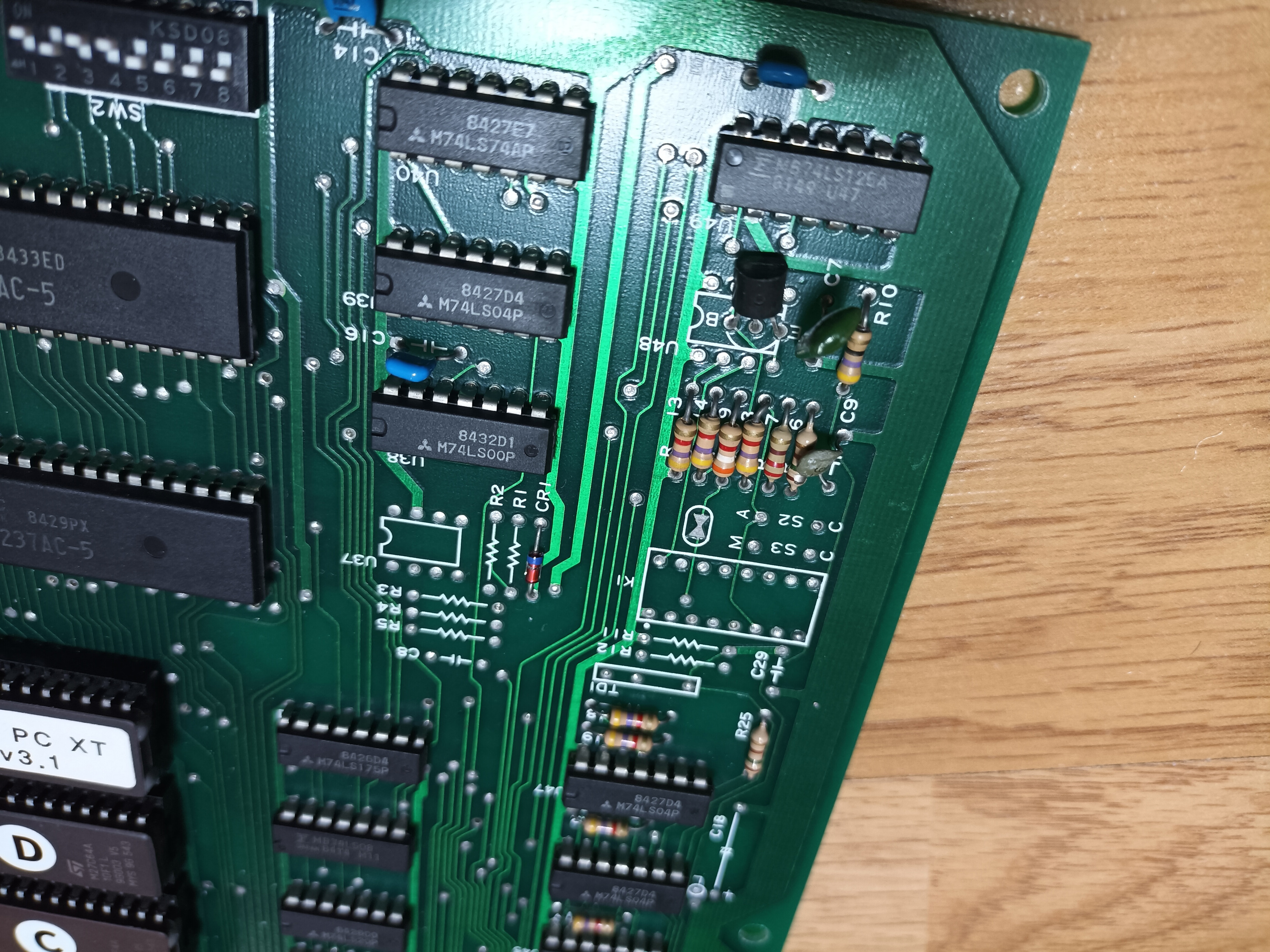
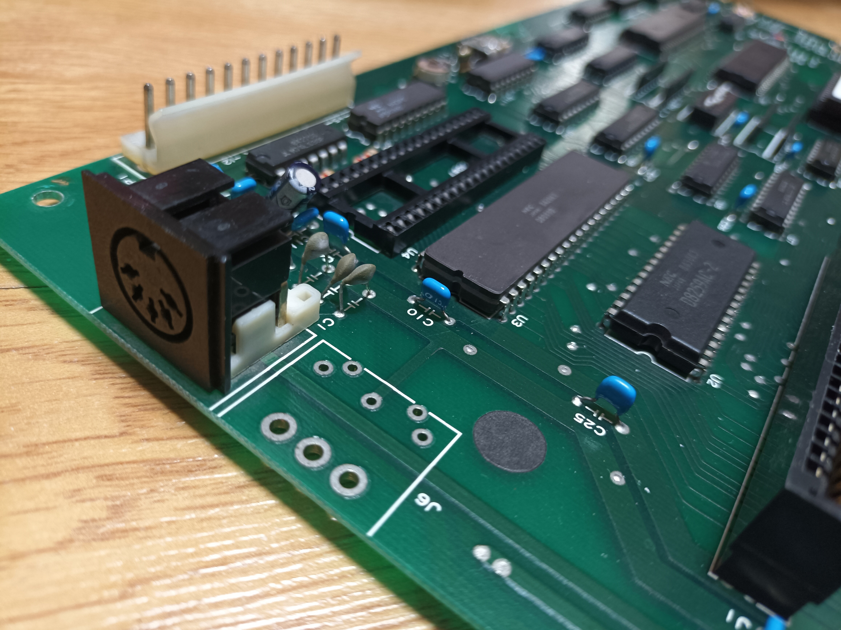
I recently acquired an XT clone motherboard, which appears to have been sold by a company called Pax Electronica Japan. There are three notable aspects about it: its layout closely resembles that of the IBM 5150 motherboard, it lacks RAM sockets, and it shows traces of what seems to be a cassette port.

When I first inspected this motherboard, I found that the original system BIOS ROM chip was faulty, so I replaced it with a new ROM chip loaded with the Super PC/Turbo XT BIOS. I also installed system memory using a MEMO-576 card, and the motherboard now functions correctly.

However, I'm curious if it's possible to revive this cassette port. What steps could I take to attempt this?

1
  • 1
    That's a beautiful board, clean as hell. It's been a long time since I saw an XT board as clean as that. Oh, it's brand new! === If you want to make it blossom though, don't put a cassette in it, particularly since it never had one. Instead, drop an 87 math co in that socket. Then run software that demos floating point with and w/o float h/w. I ran that test and hardware made it 9X faster. Your mileage may vary. That would be more impressive to me than booting from a cassette. Commented Nov 28 at 13:09

2 Answers 2

5

Partial answer:

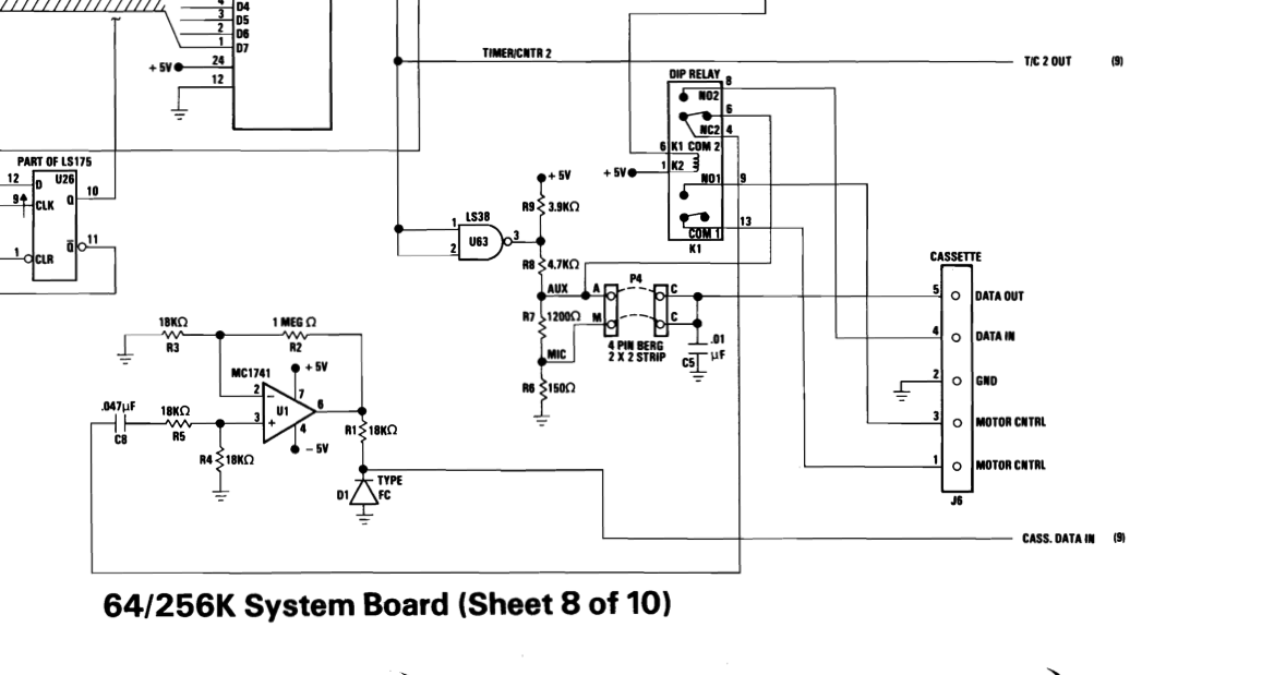
If the motherboard really closely resembles the IBM 5150 motherboard, we have schematics in the IBM 5150 Technical Reference from August 81 and April 84.

enter image description here

So you can identify the chips needed, compare with your motherboard, trace connections on your motherboard, see if the necessary chips are populated or unpopulated, and potentially add the chips and the connector to make it functional.

5
  • 4
    It might as well helpful to add the need for an XT BIOS capable of cassette handling - otherwise BASIC (or hardly anyone else) would not use it. [GlaBIOS] would be one that can be compiled with full cassette support (otherwise also a real nice one).
    – Raffzahn
    Commented Nov 5 at 19:10
  • Drats, forgot the link to GlaBIOS
    – Raffzahn
    Commented Nov 5 at 21:33
  • Would recently written XT BIOS support the cassette? It would never be needed in a business computer, which the XT wasn't, but clones were. By the time of XT clones, diskette was standard and HDD preferable. === On the other hand, the XT BIOS was created from the functionality of the published BIOS without looking at the code. So if it duplicated all functionality, it has to include the cassette. Commented Nov 28 at 12:58
  • Did you look up the FCCID of this motherboard? You can get all k, inds of wonderful information, at least when I used to sell these things In a disreputable computer store. Commented Nov 28 at 13:05
  • 1
    @MissUnderstands Yes, GlaBIOS does support the cassette interface. I'll vouch for that code being valid and working :))
    – Raffzahn
    Commented Nov 28 at 13:05
1

Without seeing the back side of the board, it does appear to match dirkt's IBM 5150 schematic:

  • The area around U37 looks like it matches the CASS. DATA IN section - 5 missing resistors, 1 capacitor, 1 diode, 1 8-pin DIP with power on pin 7.

  • K1 looks to be the relay, and the A/M/C/C pins are the Berg 2x2 pin strip for jumpers.

  • It looks like the block containing R13/R14/etc is the DATA OUT section populated with slightly different resistor values.

  • The relay coil driver 75475 has a footprint U48 but it's been replaced by a TO92 transistor.

I'm guessing TD1 and adjacent missing resistors might be a 'time delay' and something to do with video output (eg PAL), as it doesn't appear connected to the cassette block.

If the backside wiring checks out, I might be tempted to install the component values as per the 5150 schematic and give it a try.

You must log in to answer this question.

Not the answer you're looking for? Browse other questions tagged .