6

From what I understand, with floating point arithmetic, shifting values up and down is important, since a floating point value essentially is an equation like 2e×m. This supposition may be supported by browsing the floating point library for the 6502, which woz written by Steve Wozniak and Ray Rankin. I can see that there are a few loops that go round and round and lsr and lsr, to prepare the mantissas for a straight addition, and then normalises the result which involves going round and round again, this time with asl and rol. Of course, if the 6502 could shift by more than 1, that would mean a reduction in the number of shifts required.

To reduce the number of shifts in this whole process, the MANIAC-II stored only four bits for the exponent, implicitly filling to the right with zeroes. This means that the mantissa will be shifted around much further at once, which will reduce the number of loop iterations. In other words, floating point on this machine is not an equation like 2e×m, it's an equation like ce×m, where c is some constant power of two. Because apparently, on vacuum tube computers it's advantageous to reduce shifting.

What about relay computers? A relay has a much slower switching speed than a transistor (not sure how this compares with vacuum tubes), so I think some effort will have gone into reducing the number of shifts/rotations, like with the MANIAC-II. Konrad Zuse's computers all did floating point in hardware. I am interested in implementation details here. Did these computers need to shift numbers up and down, like the software implementation I linked to does? If yes, do the Zuse machines take any "shortcuts" like the MANIAC-II does?
8
  • 1
    Note that Zuse built a BCD machine in the sixties, the Z31. So not all Zuse machines were FP.
    – tofro
    Commented Nov 23, 2018 at 18:09
  • @tofro you mean the one that almost killed the company? :)) SCNR. On a more serious part, the machine wasn't developed by him and did have a different targeted market than the machines evolving from his original designs.
    – Raffzahn
    Commented Nov 23, 2018 at 18:41
  • @Raffzahn Didn't nearly all of their machines "almost kill the company"? Zuse was an engineering genius - but everything else but an entrepreneur.
    – tofro
    Commented Nov 23, 2018 at 19:00
  • The Z1: Architecture and Algorithms of Konrad Zuse’s First Computer, 2014 and Konrad Zuse's Legacy: The Architecture of the Z1 and Z3, 1996 both by Raul Rojas. The Z2 wasn't FP either. The Z3 appears to have been capable of normalization.
    – user9041
    Commented Nov 23, 2018 at 19:06
  • @tofro :)) That could be argued, as capital was always short at Zuse KG, but others did at least get a return on investment plus some profit, while the Z31 was a total failure. To be fair, the Z31 was a great design with some way unique features - like an VLIW alike instruction code and great performance, but it lackes in software support - somethin that was weak for all Zuse machines, but especially hard for a non compatible new one.
    – Raffzahn
    Commented Nov 23, 2018 at 19:07

2 Answers 2

6

Konrad Zuse's computers all did floating point in hardware. I am interested in implementation details here.

The very best way here would be Raul Rojas books. Most important:

Die Rechenmaschinen von Konrad Zuse

which goes into great details about Z1/Z3 (*1) architecture, of course focusing on the FP part, but uses mostly today's notation (*3). I'm not sure if there is an English language version available. But then there is

The First Computers - History and Architectures

a truly great collection of information about the earliest machines (*4). There is also a chapter about Z1/Z3 including a dozen or so pages about the internal/ALU structure. Not as detailed as the 'Rechenmaschinen' book, but still covering the parts you ask about.

Did these computers need to shift numbers up and down, like the software implementation I linked to does?

Yes, as they are integral to binary floating point.

If yes, do the Zuse machines take any "shortcuts" like the MANIAC-II does?

No. Or rather, it was done in a more basic and general way by adding a barrel shifter (*5). There where shifters that could move the significand up to 16 positions in a single cycle (*6). So instead of making clever workarounds to reduce shifting, he just eliminated the timing malus serial shifting carries :)) (*7)


user9041 did point out two PDFs by Raul Rojas covering the Z1/Z3:


*1 - Maybe notable here, the Z3 is a straightforward relay implementation of the fully mechanical Z1. Something I always find striking, as it not only includes many parts that have been 'great discoveries' of later developers (*2), but also prove that a modern style binary floating point computer would have been possible even before electricity.

*2 - Not just binary FP, but microprogramming, overlapping pipeline, single-step carry, barrel shifter, and more. All done by one man on a kitchen table prior to everyone else.

*3 - And explains them, when using Zuse's terms.

*4 - I think I mentioned it already but it needs to be repeated: GET THAT BOOK.

*5 - One of the speedups Intel gave to the 186/286 EU.

*6 - Again it's a bit more complex, as there are multiple shifters. Further, it was 16 positions up, 15 down. Which again may sound a bit weird considering that the significand was only 14 digits - it was used (AFAIR) for sign comparison. But I may need to check again.

*7 - Comparing the solutions is almost like looking at today's software design. If there's a problem with the implementation of a task, some will add much afterthought to build quite clever workarounds, while others just tackle the underlying issue.

1
  • Putting a barrel shifter directly in the execution pipeline was also a key feature of the ARM CPU. This meant that shifts and rotates were almost free in conjunction with some other ALU operation.
    – Chromatix
    Commented May 12, 2021 at 10:05
3

there are more solutions to speed up the bit shifts in general:

  1. align shifts to data word

    Simply use your platform WORD bit width and align your shifts to it... That means if I have an 8-bit data type I can do any multiple of 8 bit shift just by copying memory... And do the remaining bit shift one by one...

    So if our number to shift has 8*n bits and we want to shift by m bit it will lead to single array copy with relative offset of m/8 and m%8 single bit shifts.

    Here example using nibbles:

    1111 0001 1010 1100 1101 bin << 7
    1111 0001 1010 1100 1101 bin << (4+3) // ... so copy 1 Byte ahead
    0001 1010 1100 1101 0000 bin << 3
    0011 0101 1001 1010 0000 bin << 2
    0110 1011 0011 0100 0000 bin << 1
    1101 0110 0110 1000 0000 bin
    
  2. LUT

    We can have stored all the rotations in some LUT instead of rotation .. To manage modularity we can have 2 LUTs one that contains bits for the current WORDs and the second for the shifted out part ... so we can combine the results back into resulting number using OR operation...

    The LUT can be small for example we can divide the number to 4bit chunks (nibble) so we need 16 possible numbers times 4 possible shifts so 64 entries and construct any bit-shift using #1 from that.

    here some entries as example again for nibbles and 3 bit shift left

    // sh  value         H   L
    LUT[3][0000 bin] = 0000 0000
    LUT[3][0001 bin] = 0000 0100
    LUT[3][0010 bin] = 0000 1000
    LUT[3][0011 bin] = 0000 1100
    LUT[3][0100 bin] = 0001 0000
    LUT[3][0101 bin] = 0001 0100
    LUT[3][0110 bin] = 0001 1000
    LUT[3][0111 bin] = 0001 1100
    ...
    

    both #1 and #2 can be combined leading to single pass O(n) complexity (single n iterations loop without any conditions just a memory access + AND of H,L parts to connect the chain... )

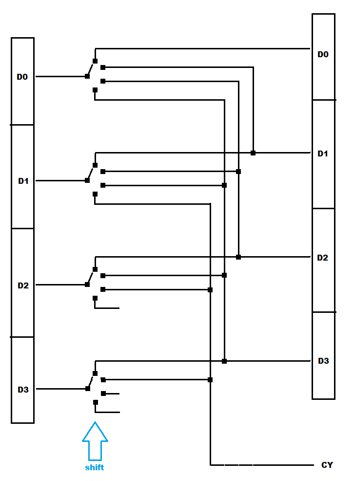
  3. parallel demultiplexors

    These do the bit-shifting of a bus between source and target buffer in one clock cycle... These were used also back in the Relay days for telephone dialing see:

    Digital demultiplexors are common and if we have enough gates to spare its possible to implement fast bit-shifts with them.

    The draw back of this implementation is that you need to have additional buffer/register which is not the case in daisy chained bit-shift register.

    parallel demultiplexors

3
  • 2
    This answer would be better if you could be explicit about which of these techniques apply to the Konrad machines. Commented Nov 23, 2018 at 19:52
  • @Wilson I am not familiar with the inner workings of the architecture but all of them are applicable ... that is why they are general methods of implementing fast bit-shift... As the architecture is relay based the #3 should be the best option (in respect to relays count vs speed)
    – Spektre
    Commented Nov 23, 2018 at 22:07
  • 1
    Reviewers: What I know about the Konrad machines, this answer is applicable to them. They had no stored software, instead they used a data flow network or computing nodes. Please "Looks Ok".
    – peterh
    Commented Aug 18, 2020 at 8:59

You must log in to answer this question.

Not the answer you're looking for? Browse other questions tagged .