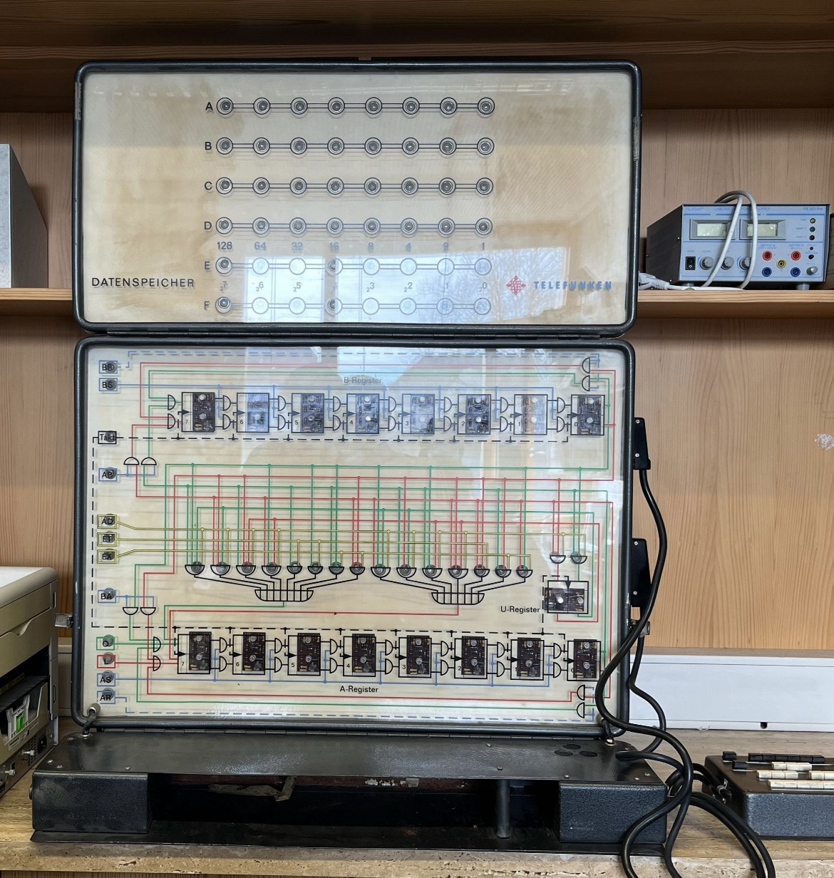
It's a Demonstrator for an ALU and Memory.
It's a serial ALU with registers, data path and a 6 byte storage, falling short to be a CPU.
An ALU (German as well ALU, sometimes 'Rechenwerk') is a function unit to combine two inputs, usually called A/B, according to defined rules into an output (called C).
The whole setup is somewhere half way between an ALU, a CPU and a computer as it additionally features registers and memory and data paths between them, but falls short of having a program sequencer or storage. Except for the memory it's best described with the German term Rechenwerk - Execution Unit in today's view (although that being defined slightly different).
If it had an instruction unit, all of the buttons would be control lines from an instruction decode stage (Befehlsdecoder) (or a horizonal code word) setting the behaviour of each element for one execution cycle (Befehlsausführung).
Please Note All of the below are assumptions made from the pictures shown so take it with an appropriate amount of caution.
We found this device in our school.
Neat, would love to have something like that at our museum.
Does anyone know what this can do exactly, and how it could work?
It seems like a simple Serial ALU. Operation get put in at AT/ET/EX, Data from A register or O/L and B-Register.
Schematics are DIN 40700 based
The best way to look up the exact function would be reading the schematics, which are printed right on top. The equations are rather straight forward as it's build from only AND, OR and FlipFlop. The schematic language is used according to DIN 40700 (*1):
AND (Und)

OR (Oder)

FlipFlop (Bistabile Kippstufe)

(Most likely of the shown JK type)
We managed to input values into the bit storage on the top, but nothing more. Can we calculate things by using the registers?
As far as I can tell, yes.
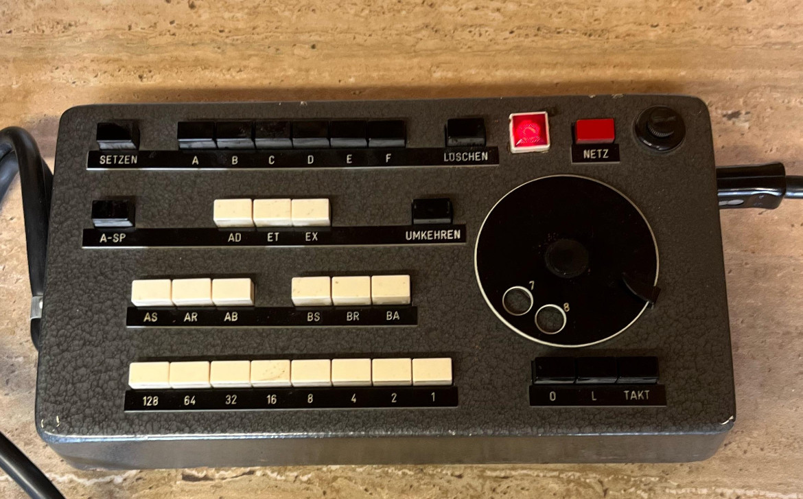
It would be already helpful to know what the symbols like AD, EX, AS,… mean. Or the dial with just 7 and 8 on it.
Operator Table
First estimate for all buttons
- Top Row - Memory Access
- SETZEN -> Wert Speichern (Set)
- A..F -> Speicheradresse (Storage Address Selection)
- LÖSCHEN -> Löschen (Clear)
- Second Row - Function
- Block 1
- A-SP -> A - Speicher (A - Storage)
- Block 2 - ALU Operation
- AD -> Addition (Addition)
- ET -> Et (&) (See Below)
- EX -> EXclusive oder (exclusive or)
- Block 3
- UMKEHREN Richtung Umkehren (Reverse Direction) (See Below)
- Third Row - Register Transfer Operation
- Block 1 Data - Operation on A
- AS -> A Setzen/Speichern (Set A)
- AR -> A Rückführung (Cycle A back to A)
- AB -> A nach B (Move A to B)
- Block 2 Data - Operation on B
- BS -> B Setzen/Speichern (Set A)
- BR -> B Rückführung (Cycle B back to B)
- BA -> B nach A (Move B to A)
- Fourth Row
- Left (Main) block - Data Input
- 1..128 -> Input Data Value
- Right (Below Dial) - Single stepping
- O -> Single Bit Data Input (See Below)
- L -> Single Bit Data Input (")
- TAKT -> Tact, one clock pulse
ET is Latin for 'and' and the German name for the '&' symbol, commonly known as 'Und' (And) Symbol or 'Kaufmännisches Und' (Commercial And) or 'Firmen-Und' (Company-And) as it's often used in company names.
UMKEHREN is 'Reverse Direction' (*2). A mystery first. Considering it being located in the function control row and coloured black like A-SP, not white like the ALU functions, it might be about memory transfer direction. That would make sense by assuming that pressing A-SP connects lines O/L to the memory and UMKEHREN defines direction. When not pressed A transfers to memory, pressed transfers memory to A.
Connecting the memory for reading and writing at O/L als resolves why there are no other connections visible used for writing (*3). Except that the circuitry as drawn does not allow to read A at O/L. So while the operation seems plausible, the location memory writes are connected is still unclear.
The Dial works as clock circuit. A rotary dial emits 1..10 of pulses according to the value dialled (10 = 0). thus 7 and 8 are there to emit 7 or 8 clock pules. The other values are simply blocked as they make no sense with an 8 bit system.
On the main table O/L are data entry lines to feed the A register an external value. Most likely those two buttons enable loading of the value selected at the fourth row (or from memory).
Combined with the TAKT (tact) those buttons may work as a single step clocking instead of using the dial to handle a full 8 bit word at once. If that's true, then pressing TAKT will give a single clock pulse, while O/L can provide a single bit input value - if needed according to transfer mode setting (see above). This also explains why they are located at the dial - aka the central clock generator:)
Main Table
The main table is structured in three blocks:
- B-Register at the top
- ALU in the middle (kind of framed by black clock lines)
- A-Register on the bottom
All logic symbols are according to DIN 40700. All connections are colour coded using
- Red/Green for Data
- Black for Clock
- Yellow for ALU Operation
- Blue for Data Transfer Control
Buttons are coloured
- White for Data and Control Input for ALU and Registers
- Black for other all functions and
Most of the symbols at the keyboard correspond directly to the same inputs visible on the main table, except for the register name:
- A-Register -> Alu-Register, i.e. target for computation (and usually as well a source)
- B-Register -> Secondary value
- U-Register -> Übertrag (Carry)
In addition the symbols O and L on the main board seem to correspond with the data output of the memory block, as well as the single step block at the operators panel.
Memory Table
The memory table seems to be an optional add-on as the main Block only marks a single external input (O/L) and no corresponding output. At least when going by schematics. Otherwise O/L could as well be used as output to memory. Then again, mechanically the setup seems to fold into a single carrying case, right?
Function
The one bit ALU is formed by a network of AND/OR gates visible in the middle combining the operation (AD/ET/EX) with data input from A and B input (top 4 red/green lines below the B-register, coming from A/B registers) and a carry input (only enabled for additions).
C output comes from the second stage OR gates (the wide ones) and goes to the A register. A carry is created by two AND gates looking at the data value for that bit
The ALU works serial, one bit at a time. Each operation results in a new bit (shifted into A) and a carry value stored at U-Register to be used with the next data bit(s).
The A-Register holds the last result of any ALU operation and serves as A input for ALU operation. It can be feed from four sources
- Reload (feedback) of it's previous value (Enabled by AR)
- Load from B (enabled by BA)
- ALU result (lines from those wide OR-gates)
- Load from external source (lines O/L)
The later is most likely the way data is entered from console or memory. As mentioned the way (connection) data is transferred to memory is still unclear. It could as well work using O/L, but then the schematic is missing that part.
The B-register register can only be fed from the A-register or its previous value.
Both registers also feature Input Enable Function. Here xS (x=A or B) allows a register is to be set with a 'new' input value. This is important as serial operation is by default destructive, i.e if no 'new' value is selected the register will be cleared afterwards.
Operation
Operation seems rather straight forward, although it might need a few trials to get it right. Examples
Before each example/step unset all buttons.
Load A from Keyboard
- Set value on 1..128 buttons
- Set AS so A gets loaded
- Dial 8 and enjoy
Transfer A to B
- Set AB
- If the value in A is tobe retained
- Set AS to enable setting of A
- Set AR to reload A with A
- Dial 8 and watch
Add B to A
- Set AD to select ALU function for addition
- Set AS to store the result in A
- If the value in B is to be retained
- Set BS to enable setting of B
- Set BR to reload B with B
- Dial 8 and listen
And so on...
Of course fun only starts by combination - like adding two numbers is done by sequence of 1,2,1,3. You're program and sequencer of this CPU, so do your job :)
Sounds like several very engaging class hours to analyze and document that device. Lucky kids!
At that point several experiments should be done to validate above assumptions. For example storing to memory with and without AR pressed to see if the write data is taken directly from A output or at/near O/L.
Sidenote:
What I loved most is how clear and self defining the labelling is. Not just because of straight language, but equally by not using any self referencing technological terms - that kind of words "everyone knows", but in fact only experts in that area know - if at all - and use with laymen because of that assumption. Misuse being just a quantum leap away. Not so with this device.
*1 - The symbols might be a bit unusual for people grown up using US style symbols or younger folks more familiar with those square IEC boxes. German Wiki has a comparison table.
*2 - Interpreting this as reversing or inverting bits doesn't make much sense, as there is no logic visible, neither for reversing nor inverting all bits. Also reversing would be 'Umdrehen', while inverting is 'Invertieren' in German
*3 - Too bad as it would prohibit any exchange operation.


