TL;DR - Yes, you could
No, as it was a clever hack that caused a colour depth change, rather than a wholesale mode change.
It might be possible to find/create a different hack to mix mode 7, but it's not possible to use the "Elite" method effect such a mode mix.
A detailed description of how the split-mode works is given here, The split-screen mode, the relevant parts of which are as follows:
It wasn't strictly Mode 4
At least not on the BBC (although the Electron did use the standard mode 4 but without the split screen)
Elite's screen mode is a custom mode, based on mode 4 but with fewer pixels. This mode is set up in the loader by reprogramming the registers of the 6845 CRTC - see the section on VDU command data at variable B% for more details, but the salient part is the screen size, which is 32 columns by 31 rows rather than the 40 x 32 of standard mode 4. Screen sizes are given in terms of characters, which are 8 x 8 pixels, so this means Elite's custom screen mode is 256 x 248 pixels, in monochrome.
Use of timer T1
For the countdown itself, we use the 6522 System VIA T1 timer, which ticks away at 1 MHz, or 1 million times a second. Each screen row contains 64 characters, or 64 * 8 = 512 pixels, and in mode 4 pixels are written to the screen at a rate of 1MHz, so that's 512 ticks of the timer per character row.
This means for every screen refresh, all 39 lines of it, the timer will tick down from 39 * 512 = 19968 ticks. If we can work out how many ticks there are between the vertical sync firing and the screen redraw reaching the dashboard, we can use the T1 timer to switch the colour depth at the right moment.
Switching colour depth
As can be seen, when the timer reaches the critical point, the colour depth is changed:
When the timer hits zero it generates an interrupt, which triggers the code in IRQ1 to reprogram the Video ULA to switch the number of colours per pixel from 2 (black and white) to 4, so the dashboard can be shown in colour.
The point being that it was a (relatively) simple change in colour depth alone.
Mode 7 is not bitmapped
However, a switch to Mode 7 would have required a wholesale change to the display, from bitmapped to "teletext". From MODE7:
The behaviour of Teletext is different from the bitmapped MODEs; the SAA 5050 chip is driven by 'ASCII' (-variant) bytes stored directly in memory. The text colour is changed and graphics are enabled line-by-line, using control codes that occupy a character cell. Several aspects of the display are governed by the SAA 5050; interlace is forced on, and text rows must be 20 scanlines deep as the chip contains its own line counter.
As the philosophy is different to the bitmapped MODEs, the built-in firmware does not support the Teletext features. Graphics functions (all PLOT commands, CLG, GCOL, cursor coupling, the graphics origin and graphics window) have no visible effect; furthermore the COLOUR statement and VDU 19 do not work in MODE 7.
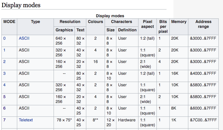
For reference, from MODE, a truncated table showing the video modes for the BBC Micro:

Further investigation
After reading Kaz's comment, I thought that a closer look was warranted.
The IRQ1
The split-screen aspect is implemented using a timer and logic in the IRQ1 interrupt handler. The timer is set when the vertical sync occurs, which happens once every screen refresh. While the screen is redrawn, the timer runs down, and it is set up to run out just as the computer starts to redraw the dashboard section. When the timer hits zero it generates an interrupt, which triggers the code in IRQ1 to reprogram the Video ULA to switch the number of colours per pixel from 2 (black and white) to 4, so the dashboard can be shown in colour. The trick is setting up the timer so that the interrupt happens at the right place during the screen refresh.
Following the IRQ1 link, we can see the two lines that set the modes (4 and 5)
 LDA #%00001000         \ Set the Video ULA control register (SHEILA &20) to
 STA VIA+&20            \ %00001000, which is the same as switching to mode 4
                        \ (i.e. the top part of the screen) but with no cursor
and then further down
 LDA #%00000010         \ Read the 6522 System VIA status byte bit 1 (SHEILA
 BIT VIA+&4D            \ &4D), which is set if vertical sync has occurred on
                        \ the video system

...

 ASL A                  \ Double the value in A to 4

 STA VIA+&20            \ Set the Video ULA control register (SHEILA &20) to
                        \ %00000100, which is the same as switching to mode 5,
                        \ (i.e. the bottom part of the screen) but with no
                        \ cursor
So, it is not just a simple colour depth change after all, but rather a "hacked" video mode change.
SHEILA &20
Looking up the SHEILA &20 register, in the BBC Microcomputer Advanced User Guide, shows:
19.1 THE VIDEO CONTROL REGISTER - SHEILA &20WRITE ONLY
This 8 bit register controls which flashing colour is present one time, whether teletext is selected, the number of characters per line, the clock rate sent to the 6845, the width in bytes of each character and the master cursor size. *FX154should be used to write data into this register.

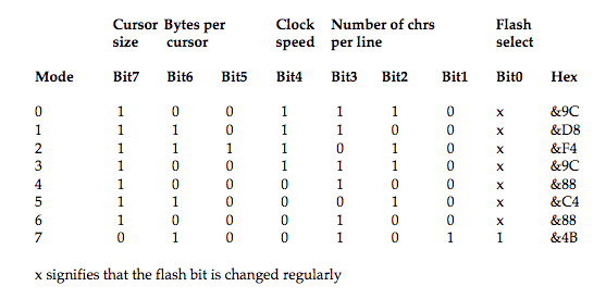
and further down the bits set per mode:
19.1.7 General summary of the video control register

So, armed with this knowledge, you could in theory, set the register to MODE 7 (without cursor), possibly using 00001011, or 01001011, like so:
 LDA #%00001011         \ Set the Video ULA control register (SHEILA &20) to
 STA VIA+&20            \ %00001011, which is the same as switching to mode 7
                        \ but with no cursor
However, the results may not be as one would expect. This code would have to be run, on an old BBC Micro, in order to see what the actual outcome was.
Additional References
These are possibly the articles in the issues of AcornUser that Chenmunka's comment refers to:
A day at the flicks
Of particular note is this paragraph on page 97 from the featured article A day at the flicks, by Peter Voke, which is about combining screen modes into dual screens, from AcornUser #52 Nov 86:
Having followed this advice, you will still find an appallingly jerky transition from the mode 7 to the dual screen. This is because the mode change needs to be done about 100 ms after the vertical sync interrupt. Since the vertical sync occurs every 400 ms, this is quite a long time. I have found that a superbly smooth transition from mode 7 to a dual mode 1 or mode 2 can be achieved with the following machine code:
LDA#19:LDX#0: LDY#0: JSRosbyteSEI: LDX#0: LDY#&A0
.wait DEX: BNEwait: DEY: BNEwait
/ the main screen switch assembly code here CLI: RTS
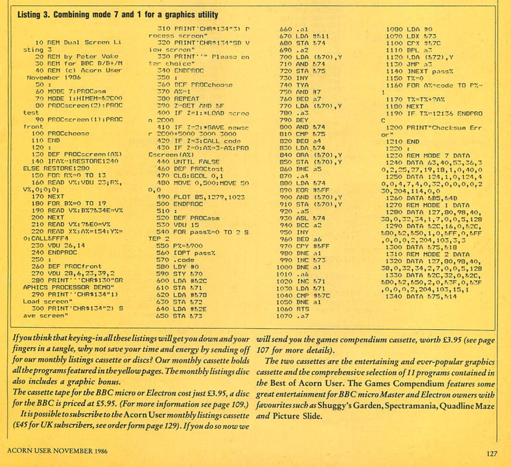
Interestingly, on page 127, some code to mix mode 1 and mode 7:


