14

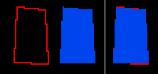
I recently noticed something in Neochrome as well as Larry Mears' "Instant Graphics and Sound" programs: Polygons have slightly different shapes depending on whether an outline is drawn or not.

I know IGS is using VDI's v_fillarea command, and I imagine Neochrome does, too.

Below is an example of a polygon I drew in Neochrome with the exact same coordinates. The red version is the unfilled, outlined version. The blue one is the filled, un-outlined version.

screenshot

I assumed the blue one would have the same shape as the red one, except with all the interior pixels filled in. But their shapes are subtly different, presumably because the fill algorithm is different from the outline algorithm (which I believe is Bresenham's). You can see this difference in the third image, where I drew the blue poly on top of the red one, allowing the red difference pixels to poke through.

Anyway, in a browser-based javascript project, I can generate unfilled polygons using Bresenham's algorithm that match the unfilled polygons I see on the ST in Neochrome or IGS. But I also need to accurately re-create the behavior of v_fillarea for making filled polygons.

I found that the source code for EmuTOS has vdi_v_fillarea and polygon functions, which attempt to recreate the original TOS routines in C ... but I don't understand what's going on in the code.

Can anyone explain VDI's polygon fill algorithm in plain language?

(FWIW, the coordinates of the polygon are: [20,10], [40,12], [42,50], [18,49])

2
  • 5
    I can't speak as to VDI, but this is usual in most APIs. The rule for triangles tends to be that a pixel is coloured if its centre* falls within the polygon (plus appropriate handling for pixels exactly on the boundary to make sure they get assigned to only one polygon), which means that a polygon can potentially be zero pixels in size. Conversely lines are always drawn a single pixel wide, usually using a rule that gives output equivalent to Bresenham.
    – Tommy
    Commented Mar 25, 2023 at 17:43
  • 1
    Saw your post on this on atari-forum, did a bit of a double take when I saw it here!
    – Matt Lacey
    Commented Apr 4, 2023 at 10:17

2 Answers 2

13

The following is from Computer Graphics: Principles and Practice by Foley, van Dam, Feiner and Hughes. Considering that this text was the "bible" of computer graphics during the 1990s, I would not be surprised if VDI was based on it or the academic papers it cites.

The book provides algorithms and explains them in ordinary language. It is too long to reprint here; it is worth borrowing or buying the book yourself. However, a few of the issues you raise can be explained here.

It's worth mentioning that back in the 1990s, computer graphics either fully painted a pixel or not. A lot of this was the result of the efficiency of algorithms on the hardware of that day. In modern times, graphics are often "antialiased", meaning that they will partially shade a pixel on the border of a polygon, depending on how much of that pixel is interior to the polygon. This results in a smoother-looking result, but takes considerably more computing time.

Much computer graphics is composed of meshes of polygons that share common edges. It is inefficient to draw the same edge twice (especially on a retrocomputer). Pixels in the interior of the polygon are painted, and there is a strategy to choose which pixels are painted on the edges. This is described in section 3.5:

Consider two rectangles that share a common edge. If we scan convert each rectangle in turn, we will write the pixels on the shared edge twice, which is undesirable, as noted earlier. This problem is a manifestation of a larger problem of area-defining primitives, that of defining which pixels belong to a primitive and which pixels do not. Clearly, those pixels which lie in the mathematical interior of an area-defining primitive belong to that primitive. But what about those pixels on the boundary? If we were just looking at a single rectangle (or just thinking about the problem in a mathematical way), a straightforward answer would be to include the pixels on the boundary, but since we want to avoid the problem of scan converting shared edges twice, we must define some rule that assigns boundary pixels uniquely.

Whilst this section is written about filled, unrotated rectangles, the authors admit that it can be generalized:

[...] it applies to arbitrary polygons as well as to rectangles.

[...] we may apply the rule also to unfilled rectangles and polygons.

(Note that today's antialiased graphics does handle boundaries twice, and no longer cares about the inefficiency of that.)

There are two ways to draw the outline of a polygon: use the same algorithm as filling the interior, or draw lines between the vertices. Section 3.6 admits that these two methods can yield different results:

With this technique, a polygon does not intrude (even by a single pixel) into the regions defined by other primitives. We can apply the same technique to unfilled polygons for consistency or can choose to scan convert rectangles and polygons a line segment at a time, in which case unfilled and filled polygons do not contain the same boundary pixels!

This is why your polygon outline and interior don't match up -- they are using different algorithms!
3
  • This is a helpful answer, but gets more at the "why" than the "how," which is why I haven't accepted it yet. I'm holding out hope someone might explain in plain language what steps VDI takes when it renders a filled polygon.
    – Kirkman14
    Commented Mar 29, 2023 at 12:52
  • 1
    @Kirkman14 your observation was that the filled polygon was different from the outline - you want to know exactly how the polygon works and not just why it's different from the outline? Commented Mar 30, 2023 at 9:14
  • @user253751 My question is titled "How does the Atari ST's VDI polygon filling algorithm work?" and I ended it by asking "Can anyone explain VDI's polygon fill algorithm in plain language?" I'm not sure how much clearer I could be about what I'm seeking.
    – Kirkman14
    Commented Mar 30, 2023 at 17:30
4

I have accepted @DrSheldon's explanation as the answer to this question, and it gets at why a polygon fill routine may result in a different shape than what you would get by using Bresenham's line-drawing algorithm to draw the outer edges of the polygon.

However, for those who, like me, wanted to know specifically how VDI applied these principles, the following may be helpful.

First, the clc_flit() function in modern EmuTOS has the code which iterates over scan lines, determines where/if the polygon's edges intersect with the scan line, and which pixels between those edges need to be filled.

The EmuTOS source code says its fill algorithm is derived from the book "Principles of Interactive Computer Graphics" by William Newman and Robert Sproull. I adapted the clc_flit() function to Javascript and found that it did produce polygon fills identical to what are produced by actual TOS. Given that, I presume this book is likely also the source of the original TOS/VDI v_fillarea function.

Section 16-2 of that book, entitled "Scan-converting polygons", explains the fill algorithm in plain language.

There are a few TOS-specific nuances mentioned in the EmuTOS source code. One such note says that in "Atari TOS the fill area always includes the left and right perimeter."

You must log in to answer this question.

Not the answer you're looking for? Browse other questions tagged .