12

On an x86 chip running in Real Mode, interrupts are resolved with the help of the IVT (Interrupt Vector Table), which is an array located at address 0000h:0000h that consists of 256 entries, 32-bit addresses (segment + offset) that point to the interrupt handler code.

This page (along with many others) lists that the first user definable interrupt handler is 20h. The first 32 handlers are reserved and used for various purposes. For example, interrupt 10h is used for x87 FPU exceptions, while interrupt 13h is used for SIMD FP exceptions. However, this page (along with many others, including Ralf Brown's Interrupt List) shows that interrupts 10h and 13h are defined by the BIOS for video and disk services, respectively. Is there something I am missing, or are these interrupt addresses used for both hardware and software interrupts at the same time?

1

2 Answers 2

20

While the documentation for the 8088 CPU used in the original IBM PC reserved the first 32 interrupt vectors for CPU exceptions, the 8088 only made use of a few of them. When IBM designed the PC they choose to ignore this and assigned the reserved but unused vectors for their own purposes.

The original 8088 only defined exceptions for the first 5 interrupt vectors, for Divide Error, Single Step, NMI, Breakpoint, and Overflow respectively. Interrupts vectors 5 through 31 were marked as reserved in Intel's 8086 Family User's Manual:
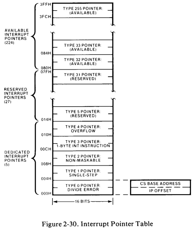
8086 Interrupt Pointer Table

Despite this, IBM decided to have their BIOS configure the interrupt controller to deliver hardware interrupts starting at interrupt vector 8. Since the original IBM PC only supported 8 hardware interrupts, this meant that vectors 8 through 15 were used for hardware interrupts. IBM then started assigning BIOS services starting with vector 16 (10h), to be invoked using software interrupts. In addition, vector 5 was used to implement a print screen function. Reserved vectors 6 and 7 weren't used.

Unfortunately this proved to be a mistake by IBM, as when Intel designed the 80286 they defined additional CPU exceptions in the reserved range, going up all the way to vector 13 (0Dh). This meant the IBM PC/AT, which used the 80286 CPU but also needed to be backwards compatible with the original 8088-based IBM PC, had interrupt vectors with two different purposes, one defined by the CPU and one defined by the BIOS.

In particular, having both the print screen and BOUND violation exception using vector 5 proved to be fairly big nuisance. In theory, this shouldn't have been a problem, as any program using the the new BOUND instruction would need to install their own interrupt handler, one that could distinguish between the two sources. In practice, however the BOUND instruction ended up getting executed unintentionally by programs that had crashed and the default BIOS handler would then get stuck in an infinite loop of printing the screen.

The other conflicting uses for the vectors weren't as much of a problem, as exceptions 10 through 13 would normally only be generated in protected mode. A protected mode operating system didn't need to be backwards compatible and couldn't use the BIOS, so could reconfigure the interrupt controller to deliver hardware interrupts through vectors outside the reserved range.

The remainder of the CPU exceptions defined by later Intel processor were either also not normally generated by real mode code that needed to be backwards compatible or handled by default BIOS handlers that could properly distinguish between sources.

4
  • Obviously hindsight is 20-20, but would there have been any problem numbering external-hardware interrupts upward from e.g. 0x40, and software interrupts downward from 0xFF? Was there any advantage to using lower interrupt numbers while leaving upper ones unused?
    – supercat
    Commented Oct 12, 2020 at 16:59
  • 1
    @supercat Well, the IBM PC BIOS and other things had a tendency to use higher vector entries for storing varies pointers and other data value that weren't interrupt vectors, but yah that could've worked. I think though if IBM had decided not to use the reserved vectors they probably would've put the hardware interrupts in the 0x20-0x27 range and then had BIOS services at either 0x28+ or 0x30+. Starting with the 80286 it's actually possible to shrink the size of the IDT so it's shorter than 256 entries, but I don't think could've been usefully exploited in real-mode.
    – user722
    Commented Oct 12, 2020 at 17:45
  • The interrupt table could easily have been shrunk in real mode by starting the BIOS data area at a lower address than 0:0x400. Still, having hardware interrupts allocated in ascending fashion and software ones descending would avoid the need to decide on a limit for either "in advance".
    – supercat
    Commented Oct 12, 2020 at 17:56
  • 1
    @supercat Well, I meant exploited in some later 80286+ IBM PC compatible machine after the 8088 IBM PC with a fixed 256 entry table would've made shrinking it break something or other.
    – user722
    Commented Oct 12, 2020 at 18:04
8

In the original PC/AT Architecture, the FPU exception signal that should be connected directly to a dedicated input pin on the main CPU and should appear as INT 10h gets re-routed by glue logic to the second IRQ controller so that it appears as IRQ 13 (i.e. INT 75h) instead. Most of the other conflicting vectors are of such a nature that the hardware-defined vectors are of interest only in protected mode, and the BIOS-defined vectors only in real mode, so that usually there will be no real conflict. Basically, the whole thing is a case of IBM engineers doing things differently from what Intel engineers intended.

You must log in to answer this question.

Not the answer you're looking for? Browse other questions tagged .