TL;DR: There is not room for two instructions.
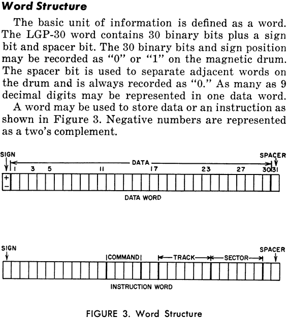
The LGP-30 word is 31 bits long. Bit 32 of a drum sector (word) is always 0. It will never be read nor operated upon. An instruction needs 16 bits, leaving 15 bits which is not enough for a second instruction.
The Details
It's Only 31 Bits
Your above calculation is about the 32 bits of a sector (drum word), not the 31-bit word the LGP-30 works on as shown in section R2.07 Number Words
   +-+-----------------------------------------------------------+-+
   |0|1 0 1 0 0 0 0 1 0 1 1 0 1 0 1 0 1 1 1 0 0 0 0 0 1 0 0 1 1 1|0|
   +-+-----------------------------------------------------------+-+
    ^                          ^                                  ^
    |                          |                                  |
 sign bit               30 magnitude bits                    spacer bit
                                                        (always 0 in memory)
and section R2.08 Number Words
   +- bit numbers ---------+-------+---+-----------+-----------+-+-+
   |0 0 0 0 0 0 0 0 0 0 1 1|1 1 1 1|1 1|1 1 2 2 2 2|2 2 2 2 2 2|3|3|
   |0 1 2 3 4 5 6 7 8 9 0 1|2 3 4 5|6 7|8 9 0 1 2 3|4 5 6 7 8 9|0|1|
   +- bit values ----------+-------+---+-----------+-----------+-+-+
   |0 0 0 0 0 0 0 0 0 0 0 0|1 1 1 0|0 0|0 1 0 1 0 0|0 0 0 0 0 0|0|0|
   +-----------------------+(-----)+---+(---------)+(---------)+-+-+
                           order bits   track bits  sector bits
                             = add         = 20        = 00
                      instruction word = a 2000
(beautification mine)
of the linked page, which is, AFAICT the 1957 Programming Manual turned into ASCII including errors (and format issues).
It's also explained on page 3 of the LGP-30 Operations Manual:

Three Bytes to the Word
When activated the tape reader will input characters until a stop code (' or 100000b) is read. Whenever a new character comes the accumulator content is shifted by the character width to the left and the new character is added to the lowest bit positions. That way a word is formed which then can be stored. Character width read can be 4 or 6 bits, depending on a switch position.
With an 18-bit instruction format of 6(4+2)/6/6, reading (and shifting) three characters, each 6-bit unit from a 6 track paper tape would look like a perfect fit, wouldn't it?
- One character for the operation, nicely selected in a way to give a meaningful mnemonic for most operations
- One character for the track number
- One character for the sector number
For example loading (bringing) a value from track 1 sector 1 into the accumulator could be (almost readably) encoded as:
b z z
Except, after reading the word would be located at bit position 13..30, not 12..29 as the instruction format asks for. But why?
Does it Compute?
Looking at the basic format, it really feels as if the whole thing was first imagined with loading instructions as three 6 bit characters in mind and then reality hit in form of wasted paper tape. To cause all 6 bits to be loaded, every input would have to be always 6 characters long (*1). Introduction of a stop character would allow words to be shortened by leading zeroes. Except that now only 31 character encodings are available (*2), meaning one sector/track address can no longer be encoded. That's losing 3% of storage. Even worse, it's spread around the address space.
Four Bits for the Rescue
Now, if the byte size switch is set to 4, only 16 characters are needed for payload, leaving 48 for control. Except, now not even the mnemonic is readable any more. At that point it may be helpful to remember that tools like Assemblers were a dream of the future, maybe good for super-computers, but not an LGP-30. Thus it was a very common idea to make the binary encoding of operations a letter that can be associated with it. The IBM 1401 encoding might be a rather prominent example, and the LGP-30 is kind of its little brother.
Except, that wouldn't work out with 4-bit encoding as the opcode would be spread over two characters - at least if the instruction occupies bit position 13..30. Shifting the decoding by one (to 12..29) would make the opcode still readable. So add track 27 sector 10 would become
a 1 g 2 8 '
Not great, but one could at least get a rough idea what the program is doing by looking dumping the tape on the printer. Likewise, using easy-to-memorize addresses for common variables would become a habit.
Long Story Short
The single spacer bit at the end is obviously due to the fact that with 4-bit instruction encoding at least the mnemonic is still plain text, while the two spacers after the operation are a leftover from a symmetric 6 bit structure.
*1 - The 31st bit would need the 6th just for itself.
*2 - The ever lasting curse of in-band-signalling.
