The manual says that the branch instructions do not affect the carry flag. However, my understanding is that some carry handling may be required when adding the relative branch offset to the program counter in order to calculate the branch destination address.
It seems you're mixing up the Carry Flag within the status register with the Carry Output of the ALU.
- The Carry Output is generated whenever an ALU operation is performend,
but
- the Carry Flag within the status register is only updated from carry output for certain operations (like mentioned in the manual).
Where is this temporary carry bit stored?
There is no temporary storage - there is only an output at the end of an ALU operation.
- When the ALU is used to perform an ALU related instruction (ADC/SBC/ROL/ROR/...) the carry output gets copied into the status register.
- When the ALU is used to calculate an address, carry output is used by the control logic to detect carry has happened, which in turn inserts another cycle to increment the high part by one, which during its execution simply ties carry input to one(*1).
Also, it seems to me the same situation occurs when using the abs,X/Y addressing modes.
The address case happens whenever a page boundary is crossed. Either by a relative branch adding the signed branch offset to PC or by an unsigned indexing operation. Affected addressing modes are
- Relative
- Absolute, X
- Absolute, Y
- Indirect, Y
As all of them may result in crossing a page as soon as the sum of the lower byte of the address plus the index value exceeds 255 (*2).
X, Indirect, Zero page, X and Zero page, Y are not among them, as here the generated address will simply wrap.
Where to Find It
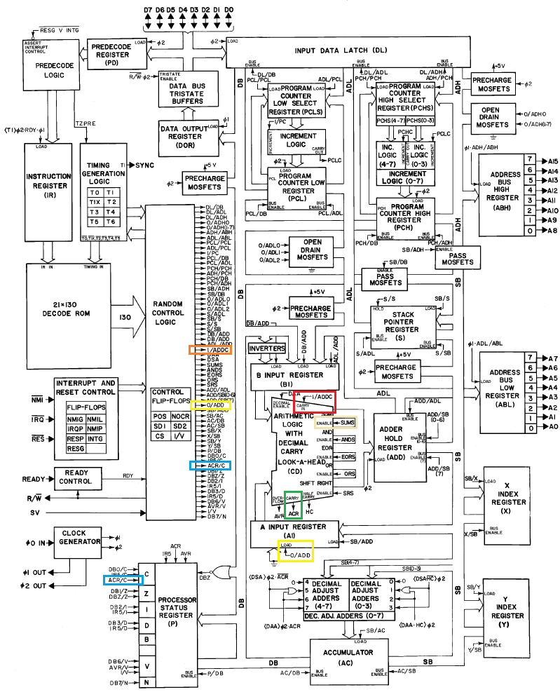
When looking at Hanson's famous drawing

(Taken from the cleaned up version on his site)
the various connections are well marked:
- [green] Carry Output, from the ALU, called
Carry, is visible at the lower side of the ALU, it creates a signal called ACR
- [blue] It gets moved into the Carry Flag when the signal
ACR/C gets activated by the control logic (the connection of ACR to Cis implied)
- [red] Carry Input is transferred from control logic to the ALU via the signal
I/ADDC
- [orange]
I/ADDC is generated by the control logic either
- by copying the Carry Flag, in case of an arithmetic operation, or
- by setting it always to one during the additional cycle of a page crossing to generate an increment (*3), or decrement in case of a relative jump backwards (*4).
*1 - It helps to keep in mind that an operation does not depend on where an information is stored, but that its signification is available when needed. There is no need to hold a dedicated carry flag in case of a high byte correction, as doing so already implies the existence of a previous carry
The best optimization of storage is to not need it..
This might of course be displayed different in a text book :))
*2 - Or goes below zero in case of a branch with negative value.
*3 - This works like any other increment by putting the value to be incremented into the B Input Register, clearing the A Input register (via 0/ADD [yellow]), setting carry (I/ADDC) and selecting the result of an addition as output (SUMS [beige]).
*4 - Detection and execution of a backward branch is a bit more complicated, but essentially the same, so let's spare that for simplicity.
